Light scattering apparatus, light scattering measurement method, light scattering analysis apparatus and light scattering measurement analysis method

a light scattering apparatus and light scattering technology, applied in the direction of measurement devices, instruments, scientific instruments, etc., can solve the problems of no practical use known currently, no method exists to accurately evaluate such a component, and the difficulty of measuring a structure using ligh

Inactive Publication Date: 2006-03-02
GEL DESIGN
View PDF1 Cites 20 Cited by
  • Summary
  • Abstract
  • Description
  • Claims
  • Application Information

AI Technical Summary

Benefits of technology

[0013] It is another object of the invention to provide an inexpensive practical light scattering analysis apparatus and light scattering measurement analysis method for calculating a photon correlation function from time-series data of photon pulses measured in light scattering.

Problems solved by technology

Generally, measurement using light is difficult to measure a structure under wavelengths of the light in principle.
For example, as a practical application, it has been tried earlier applying the dynamic light scattering method to measurement of transparent samples with complicated structures such as liquid crystal, gel and colloid, but, no practical use has been known currently.
This is because scattered light from liquid crystal or gel inevitably includes an excessive component caused by inhomogeneity of an internal structure, and there is a problem that no method exists to evaluate such a component accurately.
However, the aforementioned methods are not effective as a method for measuring an internal state of an opaque gel substance or colloidal solution including food such as milk and pudding and cosmetics such as shampoo and conditioner.
In the dynamic light scattering method, measurement of a fine internal structure is easy in transparent samples using visible light, but difficult in opaque samples (including samples with high turbidity).
However, it is known that the former is complicated and expensive and therefore not spread widely, and that the latter is commercially available, but cannot obtain accurate measurements because the means for overcoming the problem is too simplified.
Determining the number of scattering times N is difficult both theatrically and experimentally, and therefore, examining internal thermal motion is difficult in principle in a state where multiple scattering occurs.
Accordingly, even if a method is established of assuming the number of scattering times N experimentally, problems arise such that an internal structure is only determined within some error range in existing theories even using such a method.
A specific analysis apparatus has widely been used in processing of time-series data for accurate measurement, is high in evaluation, but expensive.
The analysis apparatus is a light scattering dedicated calculator in which all calculation portions are made of logic circuits (so-called full-logic), which are complicated circuits, resulting in limitations in reduction in manufacturing cost.

Method used


Image

  • Light scattering apparatus, light scattering measurement method, light scattering analysis apparatus and light scattering measurement analysis method
  • Light scattering apparatus, light scattering measurement method, light scattering analysis apparatus and light scattering measurement analysis method
  • Light scattering apparatus, light scattering measurement method, light scattering analysis apparatus and light scattering measurement analysis method

Examples


examples

[0152] Described below are results of specific measurement.

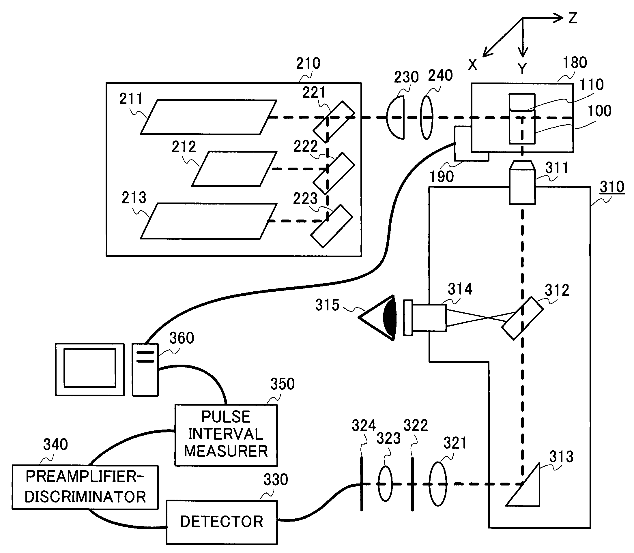
[0153] Experiments were carried out using the light scattering apparatus shown in FIG. 3 as an example. Components used as the structural elements as shown in FIG. 3 will be described below.

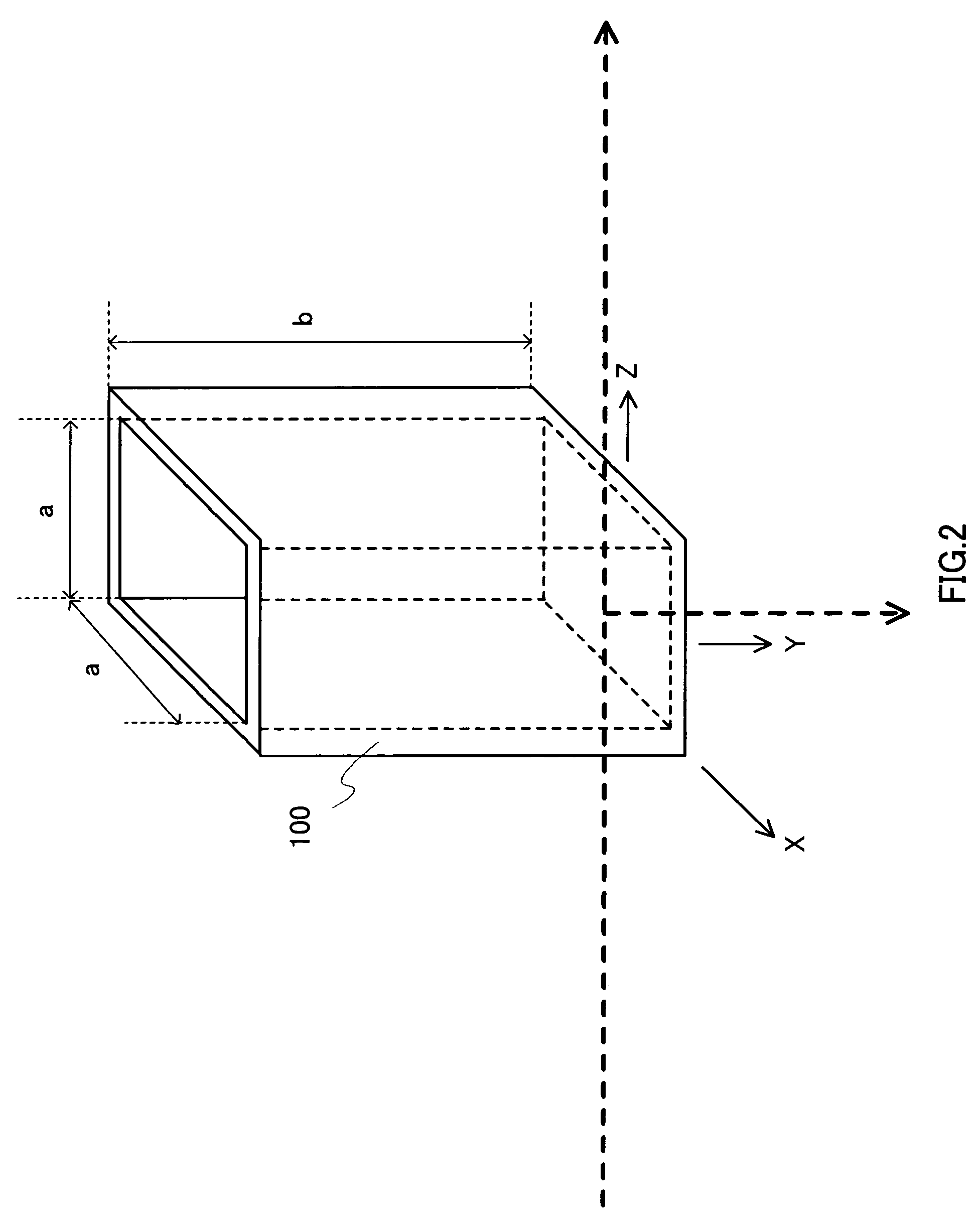
[0154] A quartz cell with five transparent faces with a size of 10 mm×10 mm×50 mm was used as sample cell 100.

[0155] Cell holder 180 was made of brass.

[0156] As control section 190, an XYZ stage was used obtained by combining three MM stages (Product number MMU-60X) of Chuo Precision Industrial Co., Ltd. The XYZ stage was allowed to perform scanning on a 1 μm basis by biaxial controller (Product number MMC-2) of Chuo Precision Industrial Co., Ltd.

[0157] As laser light source 210, used were first light source 211 that emits Helium-Neon (He—Ne) laser light (λ=632.8 nm), second light source 212 that emits semi-conductor laser light (λ=532 nm), and third light source 213 that emits Helium-Cadmium (He—Cd) laser light (λ=632.8 nm).

[0158] ...


PUM

PropertyMeasurementUnit
wavelengthsaaaaaaaaaa
sizeaaaaaaaaaa

Abstract

A light scattering apparatus capable of measuring light scattering of opaque samples. In the apparatus, control section 190 controls an optical path length required for laser light output from laser light source 210 to being incident on a sample and then outgoing as scattered light to approximate by zero. Detector 330 detects outgoing scattered light to output as a photon pulse. Pulse interval measurer 350 measures a time interval of the photon pulse output from detector 330. An operator in computer 360 calculates an n-order correlation function (n1) using the time interval of the photon pulse measured in pulse interval measurer 350.

Description

BACKGROUND OF THE INVENTION [0001] 1. Field of the Invention [0002] The present invention relates to a light scattering apparatus and light scattering measurement method, and more particularly, to a light scattering apparatus and light scattering measurement method enabling measurement even when a sample to measure is opaque. [0003] 2. Description of Related Art [0004] A dynamic light scattering method is to analyze a fine structure and motion characteristics inside a solution by measuring thermal motion occurring inside the solution through the light scattering phenomenon. Generally, measurement using light is difficult to measure a structure under wavelengths of the light in principle. However, the dynamic light scattering method is to measure an internal structure through thermal motion, and therefore, enables measurement of a fine structure under wavelengths of the light (from 0.1 nm up to and including 1 μm). Accordingly, the dynamic light scattering method using visible laser ...

Claims


Application Information

Patent Timeline
Patent Type & Authority Applications(United States)
IPC IPC(8): G01N21/00
CPCG01N21/51G01N2021/4769G01N2021/4726
Inventor FURUKAWA, HIDEMITSU
Owner GEL DESIGN
Why Eureka
Try Eureka