

Optical device, lens unit, and imaging apparatus
a technology of optical devices and lens units, applied in the direction of instruments, printers, cameras focusing arrangements, etc., can solve the problems of reducing the performance of the lens, allowing the bubbles to be trapped in the liquid container disadvantageously, and destroying the liquid container, so as to achieve the effect of maintaining the optical characteristics and reducing the size and thickness
- Summary
- Abstract
- Description
- Claims
- Application Information
AI Technical Summary
Benefits of technology
Problems solved by technology
Method used
Image

Examples
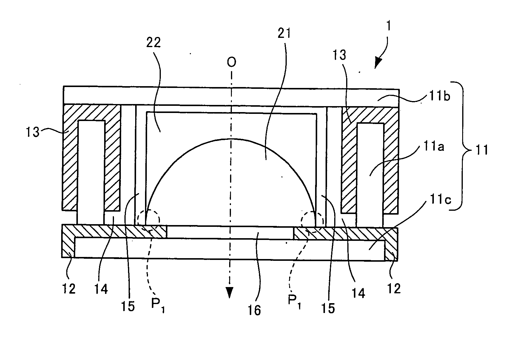
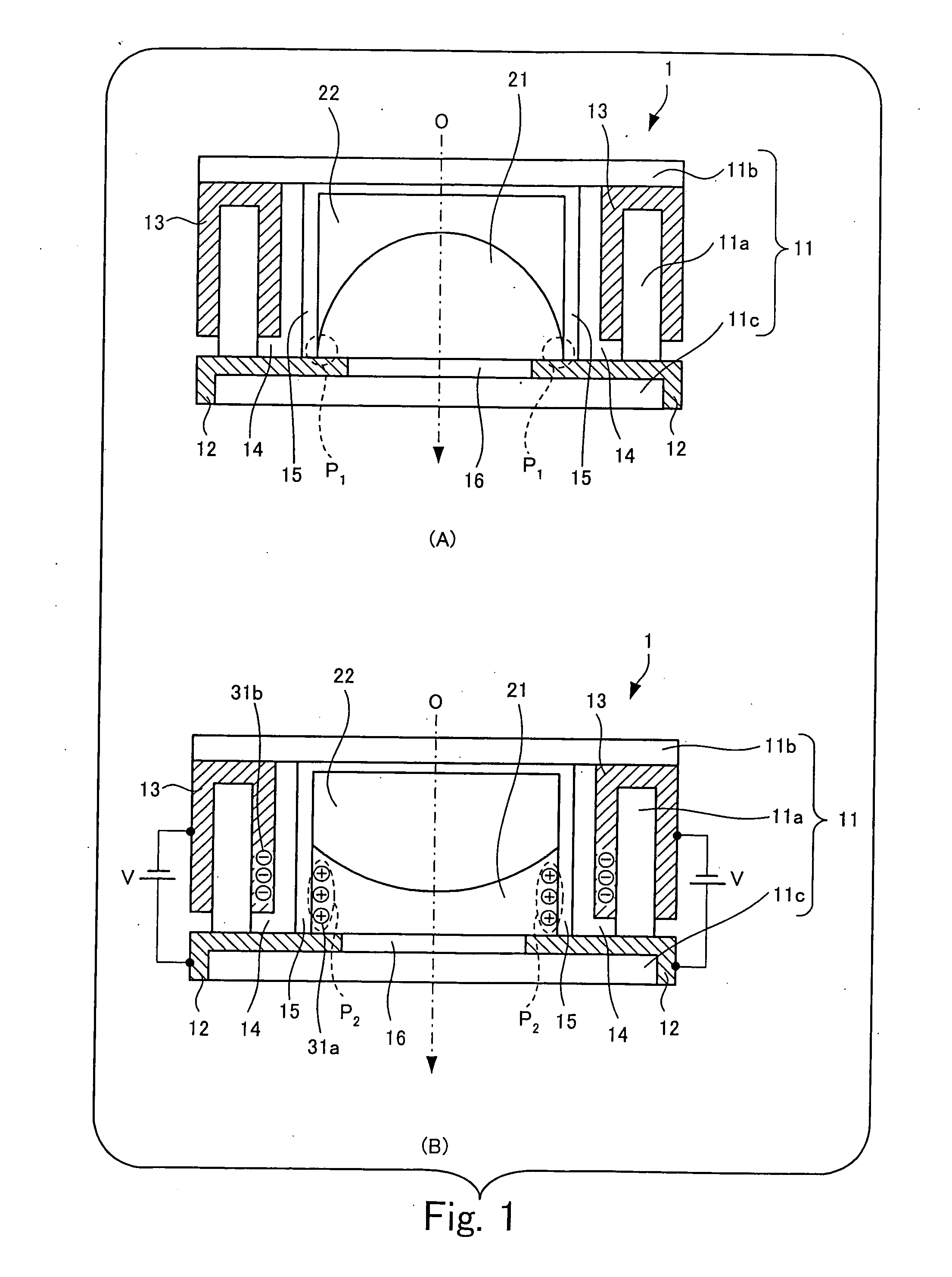
first embodiment
[0081] Up to this point the present invention has been described.
[0082] Other forms of the gas-absorbing material, different from the first embodiment will now be described using second to seventh embodiments.
[0083] The imaging apparatuses of the following second to seventh embodiments have substantially the same structure as the apparatus of the first embodiment. The descriptions of the same parts designated by the same reference numerals as in the first embodiment are not repeated, and only different points will be described below. In the focus lens of the second to seventh embodiments, object light comes in the direction indicated by arrow O from the left of the figures, and the side (left) into which light comes is the front and the side (right) from which the light goes out is the back, as in the first embodiment.
second embodiment
[0084]FIG. 5 is a schematic illustration of the structure of a focus lens according to the
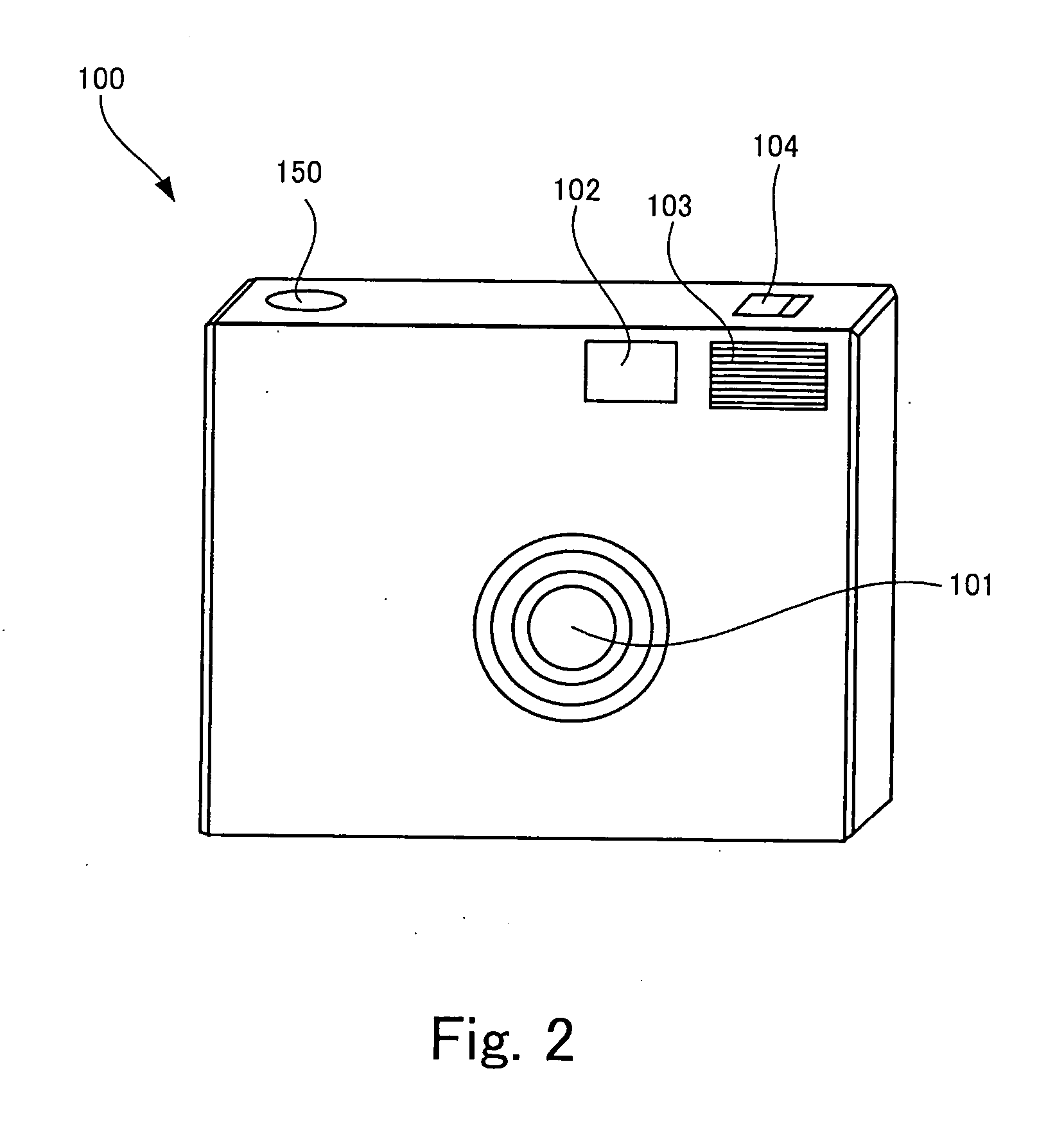
[0085] The focus lens 214 shown in FIG. 5 is incorporated in the optical shooting system 110 of the digital camera 100 shown in FIG. 3, as an alternative to the focus lens 114.
[0086] In this focus lens 214, a gas-absorbing member 402 in contact with the liquid is provided at the front side in the liquid container 201. The gas-absorbing member 402 of the second embodiment is made of carbon nanotubes (for example, produced by Aldrich) having a high hydrogen absorption capacity and is fixed to the water-repellent film 205 with, for example, an epoxy resin. This gas-absorbing member 402 is one type of the gas-absorbing material used in the present invention.
[0087] Since the gas-absorbing member 402 in contact with the liquid is provided in the liquid container 201, gas in the liquid container 201 is efficiently absorbed by the gas-absorbing member 402 before the gas turns into bubbles. The trappi...
third embodiment
[0088]FIG. 6 is a schematic illustration of the structure of a focus lens according to the
[0089] The focus lens 314 shown in FIG. 6 is also incorporated in the optical shooting system 110 of the digital camera 100 shown in FIG. 3, as an alternative to the focus lens 114.
[0090] In this focus lens 314, the liquid container 201 has an insulating film 204 disposed between the tube 201a and the water-repellent film 205, and a first electrode 202 and a second electrode 203, as in the focus lens 114 according the first embodiment shown in FIG. 4. The first electrode 202 is disposed in contact with the liquid, surrounding the hydrophilic film 206. The second electrode 203 is isolated from the liquid by the insulating film 204. In the focus lens 314 of the third embodiment, a gas-absorbing film 403 is further provided between the tube 201a and the insulating film 204 in the liquid container 201. The gas-absorbing film 403 of the third embodiment can be formed by applying inexpensive activat...
PUM
 Abstract
Description
Claims
Application Information