This helps you quickly interpret patents by identifying the three key elements:
Problems solved by technology
Method used
Benefits of technology
Benefits of technology
[0024] This means that expensive and new components like Oscon capacitors, multi layer ceramic capacitors (MLCC) or tantal capacitors should be avoided if possible. The rule of the thumb with price sensitive electronic products is to use old fashion components which are widely available by several suppliers instead of state-of-the-art technology. The same applies to production technology where standard production machinery is widely available. The use of new technology may, however, benefit the invention and will make it possible to make the AC / DC adapter even smaller or make an AC / DC adapter of similar physical size with higher wattage.
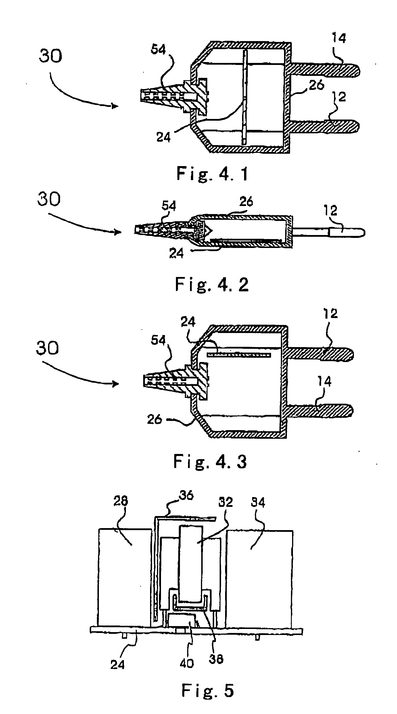
[0062] Placing the PCB perpendicular to the input connectors and perpendicular to the side surface of the plug device gives some advantages and is therefore preferred. This is not a straightforward solution because this orientation results in a smaller PCB surface area than with the other types of orientation. The arrangement of the PCB allows for the use of capacitors of radial type which usually are cylindrical and have both connectors at the same end of the component and therefore occupy a smaller space on the PCB. Capacitors with connectors at each end may also be used but they are less convenient.
Problems solved by technology
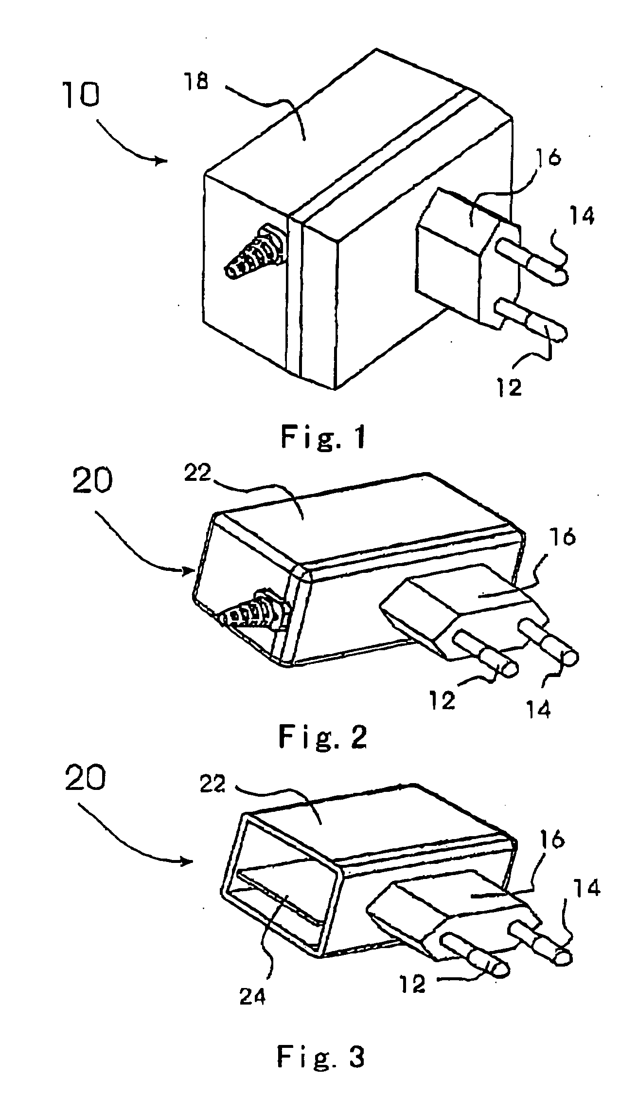
However, the latter has been accomplished with a plug device of the European type only to a degree, which primarily is due to the physical size of the converting circuit which previously tended to be large and bulky.
This also leads to a degree of over-compensation by making the components large.
The most severe drawback is that the casing is large and heavy.
Furthermore, the plug is not easily fitted into the European type sockets.
The reason is that the manufacturing cost of a SMPS adapter is still considerably higher than for a comparable linear power supply in the same wattage class.
However, this solution adds both an extra component and further disadvantages in relation to the linear type of converter.
However, the article provides no solutions to the problems associated with the small size.
However, the publication does not describe how the SMPS can be arranged inside the plug device and at the same time comply with the required standards.
Prior art AC / DC adapters have not been able to exploit the advantages of the switching technology while at the same time feature a compact design which fits into the Euro-plug for the mains.
The two main reasons are that as the dimensions shrink, a new set of problems arrive due to the required primary side to secondary side isolation and problems in relation to EMC arise due to the switching technology.
One of the problems with this type of SMPS is that the creepage and clearance distances must be approximately 5 mm in order for the product to be approved with the safety standards.
This is an expensive method for insulating the components and it is difficult to guarantee that no air pockets will occur where the liquid separates the primary and secondary circuits.
The macro-melt method may also significantly change the way the components dissipate heat.
Method used
Image
Click on the blue label to locate the original text in one second.
Reading with bidirectional positioning of images and text.
Examples
example 1
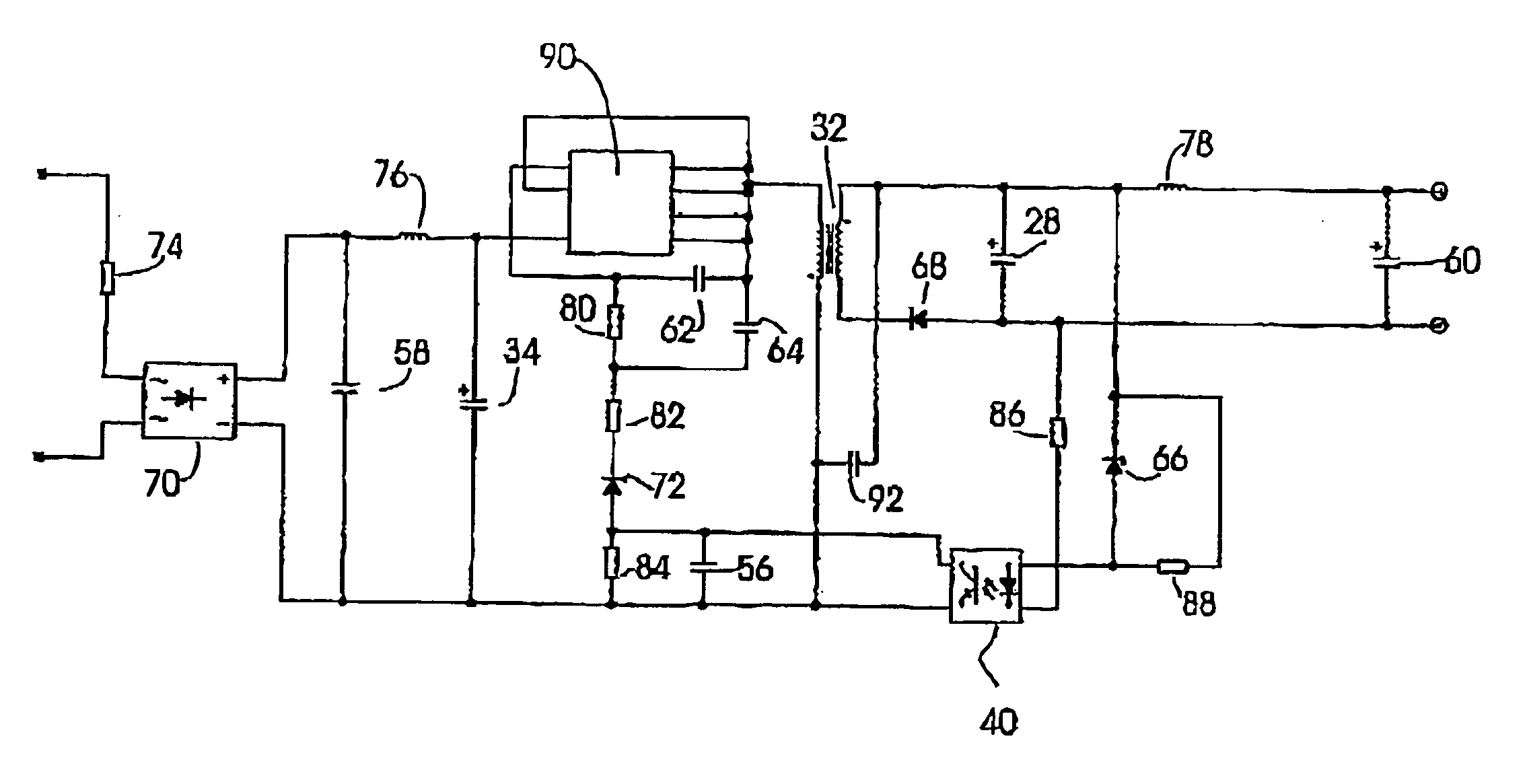
[0093] In a prototype implementation of the power supply circuit shown in 11, the following elements and components were used.
[0094] A capacitor 34,6, 8 uF, 400V, from Rubycon.
[0095] A capacitor 56, MLCC SMD0603, from Phycomp.
[0096] A capacitor 28, 1000 uF, 10V, from Luxon.
[0097] A capacitor 60, 33 uF, 10V, from Luxon.
[0098] A capacitor 58,56 nF, 1000V, from Johanson.
[0099] A capacitor 62, MLCC, SMD0603,220 nF, 50V from AVX.
[0100] A capacitor 64, MLCC, SMD1206,100 nF, 100V, from Phycomp.
[0105] A 10 ohm, 2 W, wire wound fusible resistor 74 from Token.
[0106] A RF choke 76, 1000 uH, 139 mA, from Epoos.
[0107] A chipInductor 78, 1 uH, 1000 mA, from Murata.
[0108] An optocoupler 40, from NEC.
[0109] Three resistors 80,82, 84, SMD 0603,0.063W, 50V from Phycomp.
[0110] Two ...
example 2
[0119] The above-mentioned components may also be assembled to form a transformer-based flyback switch-mode power supply circuit, omitting some components from the listing in example 1. In FIG. 12 the reference numerals refer to the components listed in example 1.
example 3
[0120] In a prototype implementation of the power supply circuit shown in 13, the following elements and components were used.
[0121] A capacitor 34,6, 8 uF, 400V, from Rubycon.
[0122] A capacitor 94, MLCC, 1 nF, 200V, X7R, from AVX.
[0123] A capacitor 96, MLCC, 100 nF, 50V, from Phycomp.
[0124] A capacitor 28,1000 uF, 10V, from Luxon.
[0125] A capacitor 60,33 uF, 10V, from Luxon.
[0126] A capacitor 58,56 uF, 1000V, from Johanson.
[0131] A 10 ohm, 2 W, wire wound fusible resistor 74 from Token.
[0132] A RF choke 76, 1000 uH, 130 mA, from Epcos.
[0133] A chipInductor 78, 1 uH, 1000 mA, from Murata.
[0134] An optocoupler 40, from NEC.
[0135] Two resistors 98,100 SMD 0805,0.125 W, 150V from Phycomp.
[0136] Five resistors 86,88, 102,104, 106, SMD 0402,0.05 mW, from Phycomp.
[013...
PUM
Abstract
A plug device with a built-in power supply of switch mode power supply type is disclosed. The plug device comprises a printed circuit board upon which a high-frequency transformer, a low-voltagecapacitor and other components which make up a switch mode power supply are arranged. A first isolating barrier extends form the housing in between the high-frequency transformer and said low-voltagecapacitor. A third isolating barrier (46) extends form the housing and into a first slot in the printed circuit board and a fourth isolating barrier extends from said housing and into a second slot in the printed circuit board. These slots are placed between the high-voltage and low-voltage connection terminals of the high-frequency transformer. A second isolating barrier extends from said housing and between the high-frequency transformer and the printed circuit board and beneath said high-frequency transformer.
Description
FIELD OF THE INVENTION [0001] The invention relates to a plug device with an built-in power supply of a switch mode power supply type (SMPS type) or a power supply unit comprising a printed circuit board (PCB) upon which a high-frequency transformer, a low-voltage capacitor and other components are arranged, said device further comprising a housing and at least two input connectors adapted for insertion into a socket such as a wall socket. [0002] All over the world different standards for electronic devices exist-though in some places the standards are considerably lower than in others-and AC / DC adapters must comply with these standards. One set of such standards are the IEC standards. IEC 60950 describes the minimum requirements for electrical equipment with regard to isolation and minimum distances between components with different voltage levels. IEC 61000 describes minimum requirements for electromagnetic compatibility (EMC). Usually, some standards are also set out for the shap...
Claims
Application Information
Patent Timeline
Application Date:The date an application was filed.
Publication Date:The date a patent or application was officially published.
First Publication Date:The earliest publication date of a patent with the same application number.
Issue Date:Publication date of the patent grant document.
PCT Entry Date:The Entry date of PCT National Phase.
Estimated Expiry Date:The statutory expiry date of a patent right according to the Patent Law, and it is the longest term of protection that the patent right can achieve without the termination of the patent right due to other reasons(Term extension factor has been taken into account ).
Invalid Date:Actual expiry date is based on effective date or publication date of legal transaction data of invalid patent.

