Fuel cell stack having improved cooling structure

a fuel cell and stack technology, applied in the field of stacks with improved cooling structures and fuel cell systems, can solve the problems of stack performance degradation and stack cooling efficiency drop, and achieve the effect of improving stack cooling efficiency and stack performan

Inactive Publication Date: 2006-03-02
SAMSUNG SDI CO LTD
View PDF1 Cites 14 Cited by
  • Summary
  • Abstract
  • Description
  • Claims
  • Application Information

AI Technical Summary

Benefits of technology

[0015] According to the embodiments of the current invention, the contact area of a coolant with the electricity generators, that also generate heat, is varied in various regions of the stack according to the temperature difference between the region of the stack

Problems solved by technology

Because the temperature difference between different regions of the unit cell is not addressed by the

Method used


Image

  • Fuel cell stack having improved cooling structure
  • Fuel cell stack having improved cooling structure
  • Fuel cell stack having improved cooling structure

Examples


first embodiment

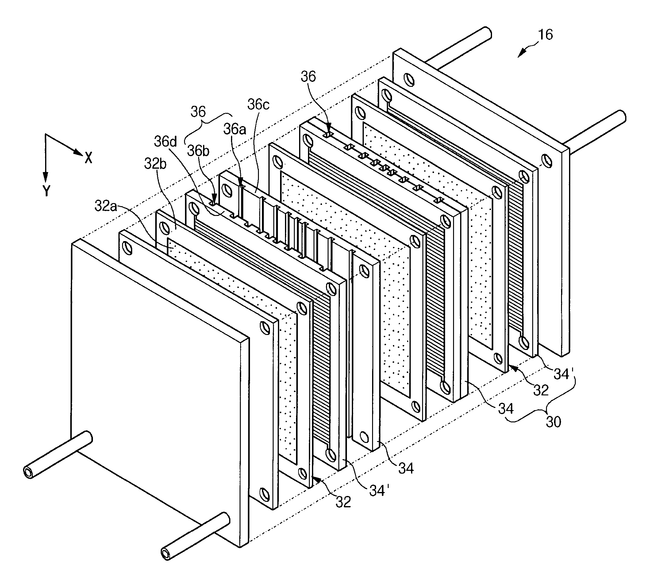
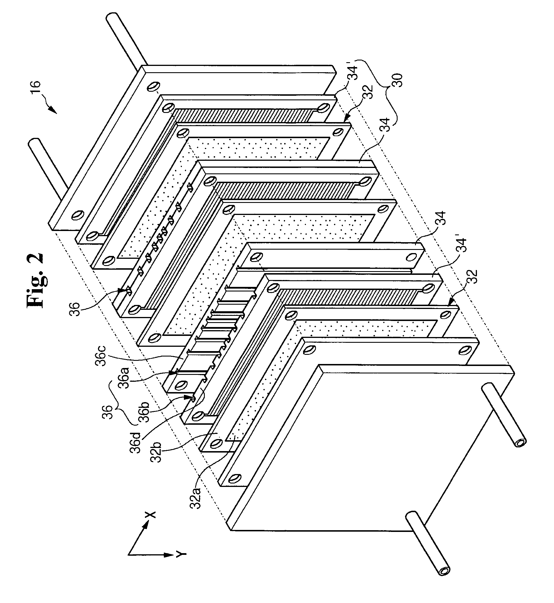
[0030]FIG. 2 is an exploded perspective view illustrating a stack 16 according to the present invention. The stack 16 in the fuel cell system 10 includes electricity generators 30 as a minimum unit generating electric energy, in which separators 34, 34′ are placed in close contact with both surfaces of a MEA 32. The separators are also referred to as “bipolar plates” in the art. The stack 16 is constructed by sequentially stacking a plurality of the electricity generators 30.

[0031] An anode is formed on one side of the MEA 12, and a cathode is formed on the other side of the MEA 12. The MEA 12 has an electrolyte membrane between the anode and the cathode. The anode receives the reformed gas through the separator 34. The anode is constructed with a catalyst layer decomposing the reformed gas into electrons and hydrogen ions and a gas diffusion layer promoting movement of the electrons and the reformed gas. The cathode receives the air through the separator 34′. The cathode is constru...

second modified embodiment

[0056] In the second modified embodiment, the shape of the cooling channels 36B changes, allowing the distribution density of the cooling channels 36B to change depending on the region of the separators 34B. This structure further improves the cooling efficiency of the stack 16.

[0057]FIG. 6 is an exploded perspective view illustrating a stack 16′ according to a second embodiment of the present invention. In comparison to the stack 16 of the first embodiment shown in FIG. 2, the stack 16′ shown in FIG. 4 further includes cooling plates 38. The cooling plates 38 are interposed between adjacent electricity generators 30′ and more specifically between the separators 37 and 37′ of two adjacent electricity generators 30′. The cooling plates 38 function as heat release plates for releasing thermal energy transferred from the separators 37 and 37′ during the operation of the electricity generators 30′.

[0058] Because the cooling plates 38 cool the entire MEA 32′, cooling efficiency is impro...

second embodiment

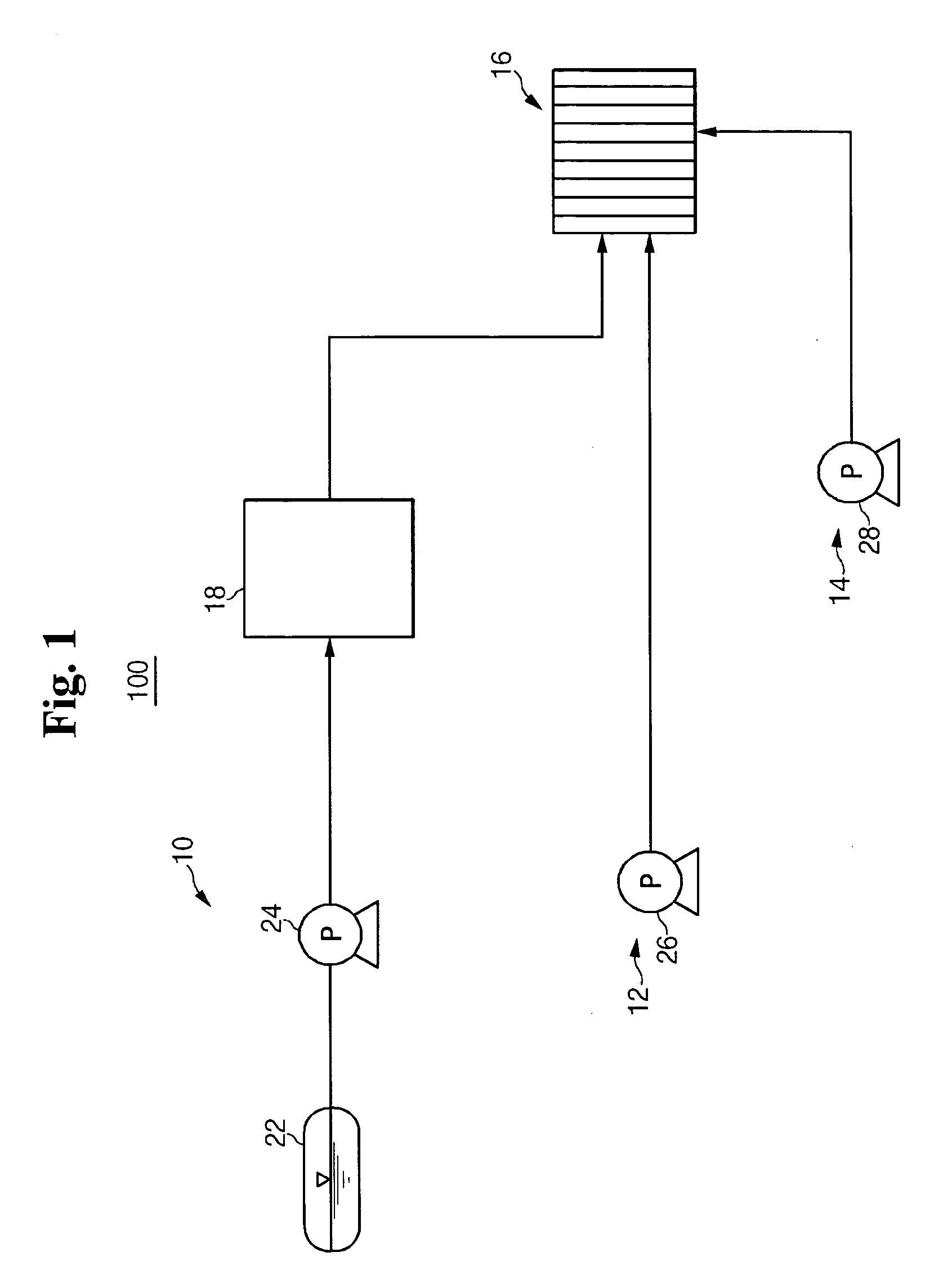
[0059] A plurality of cooling channels 36′ are formed within the cooling plates 38 and extend along one of the edges of the cooling plates 38, for example, the X direction in FIG. 6. The cooling channels 36′ of the second embodiment receive the coolant from the coolant supply unit 14 shown in FIG. 1 and cool the stack 16′. These cooling channels 36′ operate similarly to the cooling channels 36, 36A, 36B that were previously discussed. Therefore, detailed description on the construction and operations of these channels is omitted.


PUM


Abstract

A fuel cell stack that includes at least one electricity generator generating electric energy through an electrochemical reaction between hydrogen and oxygen and a cooling system are provided. The electricity generator includes a membrane-electrode assembly, separators on both sides of the membrane-electrode assembly, and cooling channels placed approximately parallel to a first direction of the membrane-electrode assembly, where a coolant flows through the cooling channels, and where the cooling channels have different distribution densities in a direction perpendicular to the first direction of the membrane-electrode assembly.

Description

CROSS REFERENCE TO RELATED APPLICATION [0001] This application claims priority to and the benefit of Korean patent application No. 10-2004-0068740 filed in the Korean Intellectual Property Office on Aug. 30, 2004, the entire content of which is incorporated herein by reference. FIELD OF THE INVENTION [0002] The present invention relates to a fuel cell system and more particularly to a stack having an improved cooling structure and a fuel cell system having the stack. BACKGROUND OF THE INVENTION [0003] In general, a fuel cell is an electricity generating system directly converting chemical reaction energy into electric energy through an electrochemical reaction between the oxygen in air and the hydrogen contained in a hydrocarbon fuel such as methanol, ethanol, or natural gas. [0004] A polymer electrolyte membrane fuel cell (PEMFC), recently developed, has excellent output characteristics, low operation temperatures, and fast starting and response characteristics. A basic PEMFC inclu...

Claims


Application Information

Patent Timeline
IPC IPC(8): H01M8/04
CPCH01M8/026H01M8/0267Y02E60/50H01M8/2405H01M2008/1095H01M8/04007H01M8/2483H01M8/0265H01M8/241H01M8/2457H01M8/02H01M8/0258
Inventor SUH, DONG-MYUNG
Owner SAMSUNG SDI CO LTD
Why Eureka
Try Eureka