Supercharge Your Innovation With Domain-Expert AI Agents!

Antistatic properties for thermally developable materials

a technology of antistatic properties and thermal development, which is applied in the field of thermal development of materials, can solve the problems of increasing the formation of various types of “fog” or other undesirable sensitometric side effects, distinctly different problems, and much effort in the preparation and manufacture of photothermographic materials, so as to improve the surface resistivity, improve the conductive efficiency, and improve the effect of conductive properties

Inactive Publication Date: 2006-03-02
CARESTREAM HEALTH INC
View PDF14 Cites 4 Cited by
  • Summary
  • Abstract
  • Description
  • Claims
  • Application Information

AI Technical Summary

Benefits of technology

The present invention provides a thermally developable material that includes a support and one or more thermally developable imaging layers containing a non-photosensitive source of reducible silver ions and a reducing agent composition for the non-photosensitive source. The material also includes a non-imaging backside conductive layer and a non-imaging backside overcoat layer. The non-imaging backside conductive layer is composed of non-acicular metal antimonate particles in a mixture of two or more polymers that include a first polymer and a second polymer. The non-imaging backside overcoat layer is made of a film-forming polymer and an antihalation composition. The material can be used for photothermographic or thermographic imaging.

Problems solved by technology

The incorporation of the developer into photothermographic materials can lead to increased formation of various types of “fog” or other undesirable sensitometric side effects.
Therefore, much effort has gone into the preparation and manufacture of photothermographic materials to minimize these problems.
Moreover, in photothermographic materials, the unexposed silver halide generally remains intact after development and the material must be stabilized against further imaging and development.
Because photothermographic materials require dry thermal processing, they present distinctly different problems and require different materials in manufacture and use, compared to conventional, wet-processed silver halide photographic materials.
The incorporation of such additives as, for example, stabilizers, antifoggants, speed enhancers, supersensitizers, and spectral and chemical sensitizers in conventional photographic materials is not predictive of whether such additives will prove beneficial or detrimental in photothermographic materials.
The accumulated charges can cause various problems.
This may result in imaging defects that are a particular problem where the images are used for medical diagnosis.
Build-up of electrostatic charge can also cause sheets of thermally processable materials to stick together causing misfeeds and jamming within processing equipment.
Additionally, accumulated electrostatic charge can attract dust or other particulate matter to the materials, thereby requiring more cleaning to insure rapid transport through the processing equipment and quality imaging.
Build-up of electrostatic charge also makes handling of developed sheets of imaged material more difficult.
This problem can be particularly severe when reviewing an imaged film that has been stored for a long period of time because many antistatic materials loose their effectiveness over time.
This also results in poor conductive efficiency.

Method used


Image

  • Antistatic properties for thermally developable materials
  • Antistatic properties for thermally developable materials
  • Antistatic properties for thermally developable materials

Examples


example 1

Preparation of Conductive Backside Materials

[0274] Conductive Backside Materials were prepared as follows:

[0275] Buried Backside Conductive Layer Formulation:

[0276] A buried backside conductive layer formulation was prepared by mixing the following materials:

[0277] Solution A:

[0278] Solution B:

CELNAX ® CX-Z641M 80 g(containing 60% non-acicularzinc antimonate solids in methanol)MEK120 g

[0279] Solution A: VITEL® PE-2700B LMW and CAB 381-20 were dissolved in 1269 g of MEK.

[0280] Solution B: CELNAX® CX-Z641M non-acicular zinc antimonate was placed in a second reaction vessel, stirring was begun and 120 g of MEK was added.

[0281] Buried Backside Layer Solution: Solution A was added to Solution B with stirring.

[0282] Backside Overcoat Formulation:

[0283] A backside overcoat formulation was prepared by mixing the following materials:

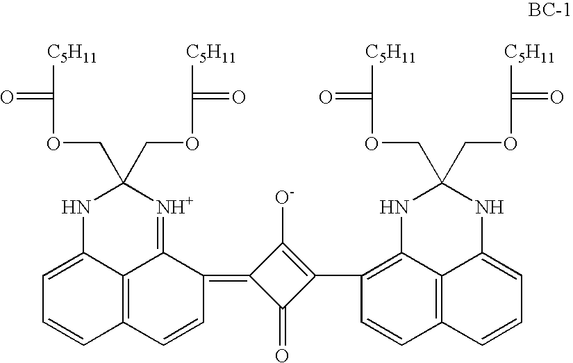
MEK88.88 weight %CAB 381-2010.98 weight %SYLOID ® 74X6000 0.14 weight %Antihalation Dye BC-1 0.07 weight %

[0284] The buried backside conductive lay...

example 2

Preparation of Photothermographic Materials

[0294] Backside conductive carrier layer and backside overcoat layer formulations were prepared, coated onto a 7 mil (178 μm) blue tinted poly(ethylene terephthalate) support, and dried as described above in Example 1.

[0295] Photothermographic Emulsion Formulation:

[0296] A photothermographic emulsion coating formulation was prepared using a silver salt homogenate prepared substantially as described in Col. 25 of U.S. Pat. No. 5,434,043 (noted above), incorporated herein by reference. The photothermographic emulsion formulation was then prepared substantially as described in Cols. 19-24 of U.S. Pat. No. 5,541,054 (Miller et al.) that is also incorporated herein by reference.

[0297] Photothermographic Emulsion Topcoat Formulation:

[0298] A topcoat formulation was prepared for application over the photothermographic emulsion formulation with the following components:

MEK86.10 weight %VS-1 0.35 weight %Benzotriazole 0.27 weight %Silica 0.21...


PUM

PropertyMeasurementUnit
thicknessaaaaaaaaaa
thicknessaaaaaaaaaa
thicknessaaaaaaaaaa

Abstract

The use of metal antimonates at high metal antimonate to binder ratios in buried backside conductive layers of thermographic and photothermographic materials allows the use of thin backside overcoat layers. The combination provides antistatic constructions having excellent antistatic properties that show less change in resistivity with changes in humidity. The thin backside overcoat layer serves to protect the buried antistatic layer.

Description

FIELD OF THE INVENTION [0001] This invention relates to thermally developable materials having certain backside conductive layers. In particular, this invention relates to thermographic and photothermographic materials having conductive backside layers that show little change in resistivity with changes in humidity. This invention also relates to methods of imaging using these thermally developable materials. BACKGROUND OF THE INVENTION [0002] Silver-containing thermographic and photothermographic imaging materials (that is, thermally developable imaging materials) that are imaged and / or developed using heat and without liquid processing have been known in the art for many years. [0003] Silver-containing thermographic imaging materials are non-photosensitive materials that are used in a recording process wherein images are generated by the use of thermal energy. These materials generally comprise a support having disposed thereon (a) a relatively or completely non-photosensitive sou...

Claims


Application Information

Patent Timeline
Patent Type & Authority Applications(United States)
IPC IPC(8): G03C1/00
CPCB41M5/42B41M5/426B41M5/44B41M2205/04B41M2205/36G03C1/49872G03C1/7614G03C1/4989G03C1/85G03C2001/7628
Inventor LUDEMANN, THOMAS J.LABELLE, GARY E.PHILIP, DARLENE F.KOESTNER, ROLAND J.BHAVE, APARNA V.
Owner CARESTREAM HEALTH INC
Features
  • R&D
  • Intellectual Property
  • Life Sciences
  • Materials
  • Tech Scout
  • Unparalleled Data Quality
  • Higher Quality Content
  • 60% Fewer Hallucinations
Learn More