Received signal strength measurement circuit, received signal strength detection circuit and wireless receiver

a technology of received signal strength and measurement circuit, which is applied in the direction of amplifier combinations, instruments, transmission monitoring, etc., can solve the problems of difficult downsizing or integrating circuits, difficult to measure, and complex circuit arrangements, etc., to achieve improved communication characteristics, stable measurement, and increased reception accuracy

Inactive Publication Date: 2006-03-02
SHARP KK
View PDF13 Cites 10 Cited by
  • Summary
  • Abstract
  • Description
  • Claims
  • Application Information

AI Technical Summary

Benefits of technology

[0024] The RSSI detection circuit or the wireless receiver including the RSSI circuit according to the present invention can stably measure the strength of a

Problems solved by technology

The change causes an error in the output from the RSSI circuit system (a result of measurement of received signal strength).
As described above, in the conventional RSSI circuit system, there is a problem that temperature dependence of an output amplitude (gain) varies greatly depending on the input level to the IF amplifier circuit 1220, with the result that output characteristics vary depending on temperature and therefore may cause error.
Further, in the conventional RSSI circuit system

Method used


Image

  • Received signal strength measurement circuit, received signal strength detection circuit and wireless receiver
  • Received signal strength measurement circuit, received signal strength detection circuit and wireless receiver
  • Received signal strength measurement circuit, received signal strength detection circuit and wireless receiver

Examples


first embodiment

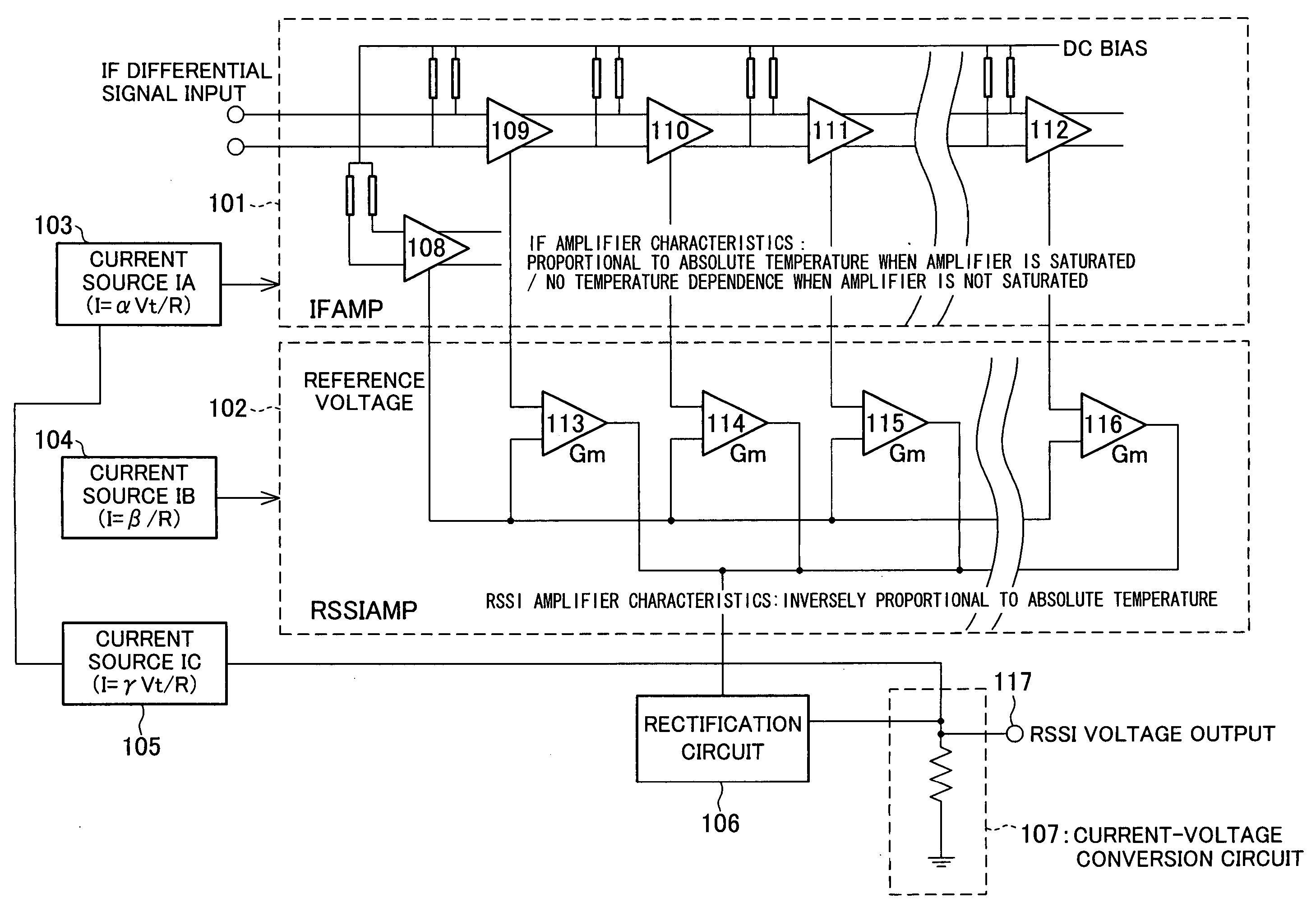
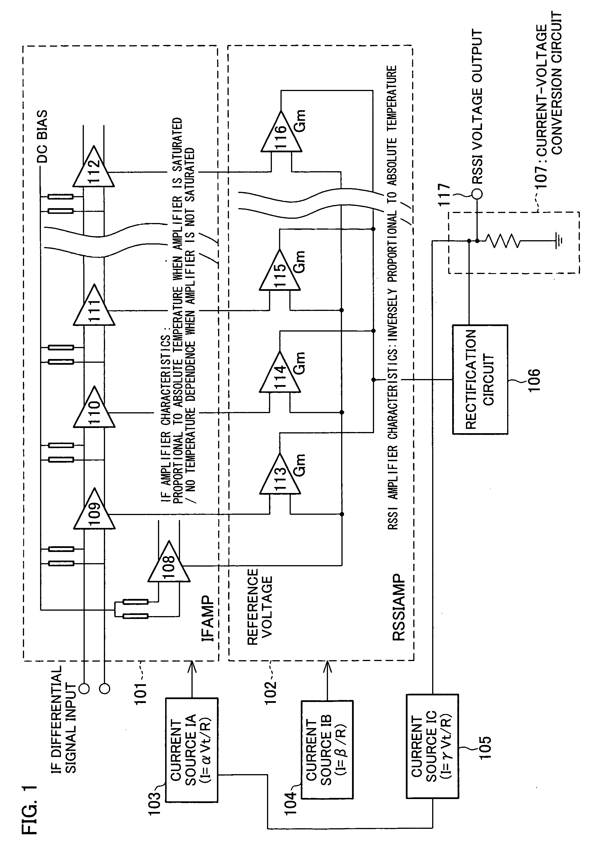
[0042] An embodiment of the present invention is explained below in detail with reference to figures. FIG. 1 represents an embodiment showing an overall structure of an RSSI circuit of the present invention. The RSSI circuit includes an IF amplifier 101, an RSSI amplifier (voltage-current conversion section) 102, a current source IA 103, a current source IB 104, a current source IC 105, a rectification circuit 106, and a current-voltage conversion circuit (voltage output section) 107.

[0043] The IF amplifier 101 is constituted by cascading plural stages of amplifiers (differential amplifiers) 109 through 112. Each of the amplifiers 109 through 112 constituting the IF amplifier amplifies an inputted signal and outputs the amplified signal to the amplifier of the next stage.

[0044] In addition to an amplifying function, each of the amplifiers 109 through 112 serves to output an absolute value signal of the magnitude proportional to an absolute value of the inputted signal. The absolut...


PUM


Abstract

The RSSI circuit of the present invention includes: an IF amplifier section, which includes multiple stages of serially connected differential amplifiers for amplifying, with use of a current source IA provided as a power source for amplification, an IF signal corresponding to a received signal; an RSSI amplifier section for converting into current a voltage amplitude of an absolute value signal outputted from the differential amplifiers of the IF amplifier section, using a current source IB provided as a power source for conversion, and adding and outputting the converted current; and a current voltage conversion circuit for converting into voltage the output current from the RSSI amplifier section, and outputting the converted voltage as a measurement voltage value. The RSSI amplifier section is set so that a current value of the RSSI amplifier section is inversely proportional to absolute temperature. With the configuration, it is possible to realize an RSSI circuit, a received signal strength detection circuit and a wireless receiver, which are able to stabilize a strength measurement of a received signal relative to a change in temperature and to increase communication characteristics.

Description

[0001] This non-provisional application claims priority under 35 U.S.C. § 119(a) on Patent Application No. 2004 / 247318 filed in Japan on Aug. 26, 2004, the entire contents of which are hereby incorporated by reference. FIELD OF THE INVENTION [0002] The present invention relates to a received signal strength measurement circuit (referred to as an RSSI circuit in general) and a received signal strength detection circuit, used for a wireless receiver and having superior temperature stability, and a wireless receiver using the circuits. BACKGROUND OF THE INVENTION [0003] Generally, in a wireless receiver, a high-frequency radio signal from an antenna is firstly converted into a signal with an intermediate frequency (IF (Intermediate Frequency) signal), and then the IF signal is amplified and inputted to a detector. In the detector, a desired signal process, namely, a detection process in which information included in the radio signal is taken out is performed. In this detection process,...

Claims


Application Information

Patent Timeline
IPC IPC(8): H04B17/00H03F1/30H03F3/45H03F3/68H04B1/26
CPCH04B17/318G01N27/12
Inventor NAKANO, YOSHIAKI
Owner SHARP KK
Why Eureka
Try Eureka