Optical element, lens unit and image pickup apparatus

a technology of optical elements and lens units, applied in the direction of cameras, instruments, printers, etc., can solve the problems of light scattering, light transmission decline, and change of the interface form of two kinds of liquids, so as to maintain light transmission and optical performance.

Active Publication Date: 2006-03-02
FUJIFILM CORP +2
View PDF16 Cites 35 Cited by
  • Summary
  • Abstract
  • Description
  • Claims
  • Application Information

AI Technical Summary

Benefits of technology

[0039] According to the present invention, it is possible to provide the optical element, lens unit and image pickup apparatus capa

Problems solved by technology

Consequently, the conductive solution starts to wet the water-repellent film covering the inner wall of the tube, causing change of an interface form of the two kinds of liquid.
Therefore, there is a problem that, if used for a long period of time, a generated gas stays in the liquid container and turns into bubbles, sc

Method used


Image

  • Optical element, lens unit and image pickup apparatus
  • Optical element, lens unit and image pickup apparatus
  • Optical element, lens unit and image pickup apparatus

Examples


first embodiment

[0085] This concludes the description of the present invention.

[0086] Here, the optical element of the present invention has an advantage that its optical performance is maintained even in the high temperature environment. A description will be given as to second and third embodiments exploiting this advantage hereunder.

[0087] First, a description will be given as to the second embodiment in which the optical element of the present invention is applied to a monitoring system having a photographic device installed outdoors. As the first embodiment and the second embodiment have approximately the same device configuration, attention is paid to a difference from the first embodiment, and the same elements are given the same symbols to omit a description thereof.

second embodiment

[0088]FIG. 5 is a schematic block diagram of the monitoring system to which the present invention is applied.

[0089] A monitoring system 400 shown in FIG. 5 is configured by connecting a photographic device 410 installed in an outdoor parking lot and so on to a monitoring device 420 installed in an observation room and so on by a network.

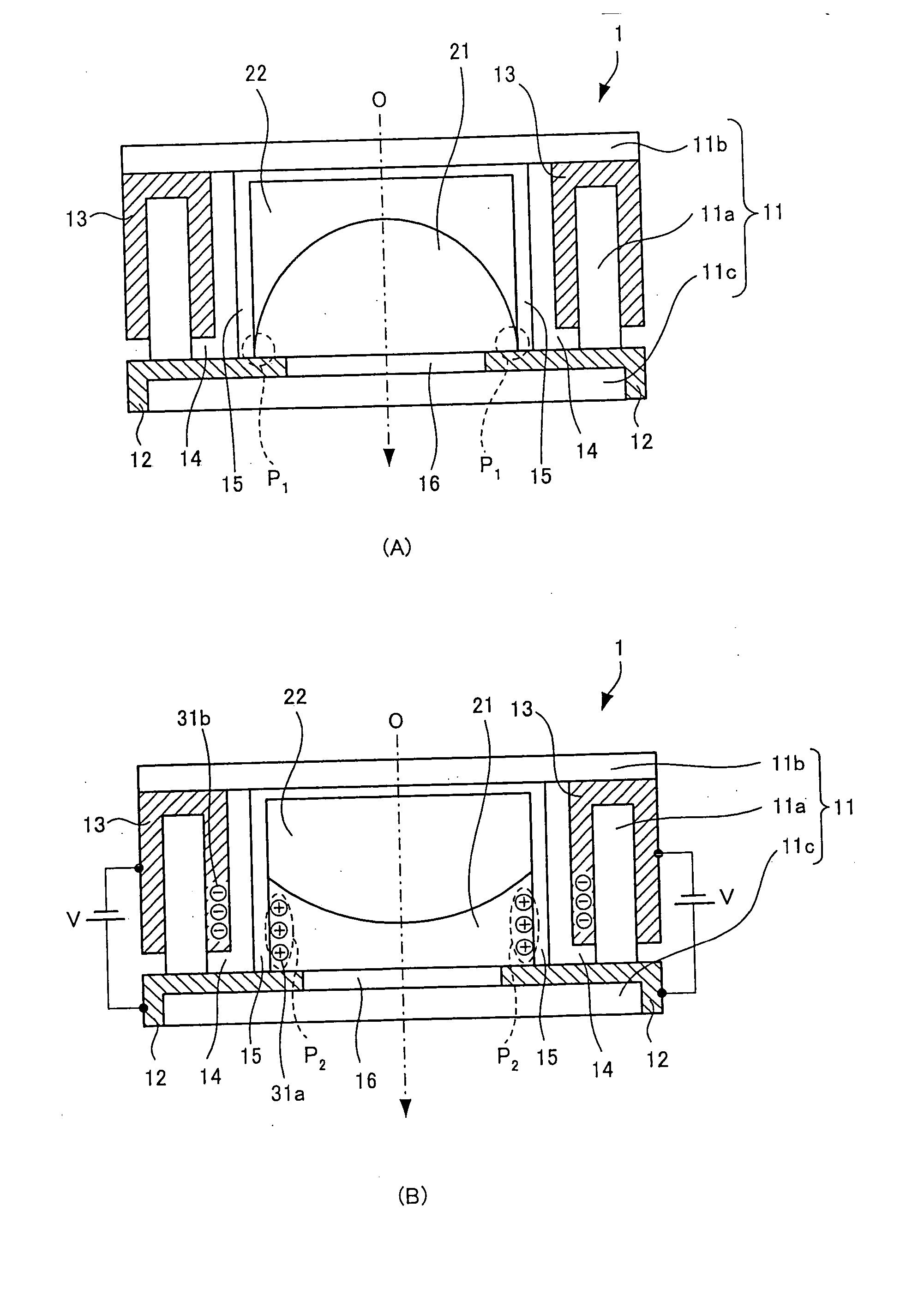
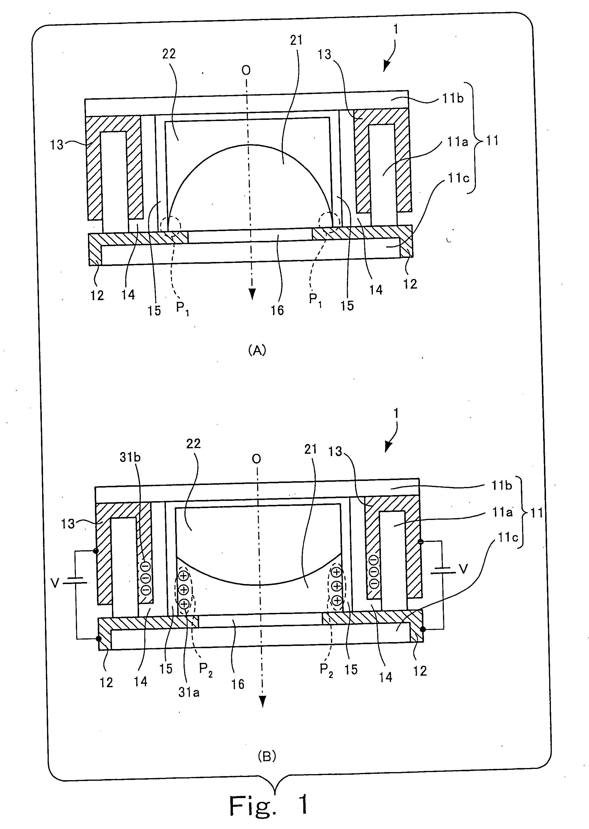
[0090] The photographic device 410 obtains various instructions from the monitoring device 420 via a motor driver 120d, and the subject is shot according to the instructions so as to generate digital shot image data. When the shot image data is generated, the voltage applied to the first electrode 202 and the second electrode 203 shown in FIG. 4 is controlled by the focus controller 114a, and the form of the interface between the ionic liquid 301 and the insulating liquid 302 is adjusted to focus on the subject. The generated shot image data is sent to the monitoring device 420.

[0091] The monitoring device 420 performs image processing to the shot ...

third embodiment

[0095]FIG. 6 is a schematic block diagram of the printer to which the present invention is applied.

[0096] A printer 500 has a control section 510 controlling various elements of the printer 500, an image processing section 520 generating the image data representing an output image, a laser emitting section 530 emitting the laser beam based on the image data, a prism 540 refracting the laser beam, and a lens 550 condensing the laser beam on paper 600.

[0097] For instance, the image data obtained by reading an original image is obtained by the image processing section 520, and undergoes predetermined image processing therein. The image data after the image processing is sent to the laser emitting section 530.

[0098] The laser emitting section 530 emits the laser beam based on the image data sent from the image processing section 520. The emitted laser beam is refracted by the prism 540 and gets incident on the lens 550.

[0099] The lens 550 has the same configuration as the focus lens ...


PUM

PropertyMeasurementUnit
Refractive indexaaaaaaaaaa
aaaaaaaaaa

Abstract

An optical element and a lens unit each includes: a liquid container transmitting light at least in a predetermined optical axis direction, the liquid container containing an insulating liquid and an ionic liquid being mutually immiscible and optically transparent, and having different refractive indices; a first electrode contacting the ionic liquid in the liquid container; and a second electrode insulated from the ionic liquid in the liquid container. The ionic fluid is not subject to electrolysis and does not evaporate easily even at high temperature. Accordingly, the optical element, the lens unit and an image taking apparatus having the optical element can maintain high light-transmission and optical characteristics over a long period even in a high temperature environment.

Description

BACKGROUND OF THE INVENTION [0001] 1. Field of the Invention [0002] The present invention relates to an optical element transmitting light, a lens unit and an image pickup apparatus having subject light focused to obtain image data. [0003] 2. Description of the Related Art [0004] There are cameras having a zoom function of freely setting a shooting field angle among electronic still cameras providing an image of a subject on a solid-state image sensing device such as a charge coupled device (CCD) and retrieving image data representing the subject as a signal and film cameras doing a photo shoot on a photographic film. Such cameras are equipped with an image taking lens of which focal length varies according to operation of a zoom switch. The image taking lens is generally a compound lens composed of a combination of multiple lens elements, where relative positions of the multiple lens elements are adjusted according to the focal length set up by the zoom switch. Such cameras have a ...

Claims


Application Information

Patent Timeline
IPC IPC(8): C08K5/13
CPCG02B3/14G02B7/102H04N5/23212G02B26/125H04N5/2254G02B13/0075H04N23/673H04N23/55
Inventor KATO, TAKASHIMASUDA, TOMONORIMIYANO, HITOSHI
Owner FUJIFILM CORP
Why Eureka
Try Eureka