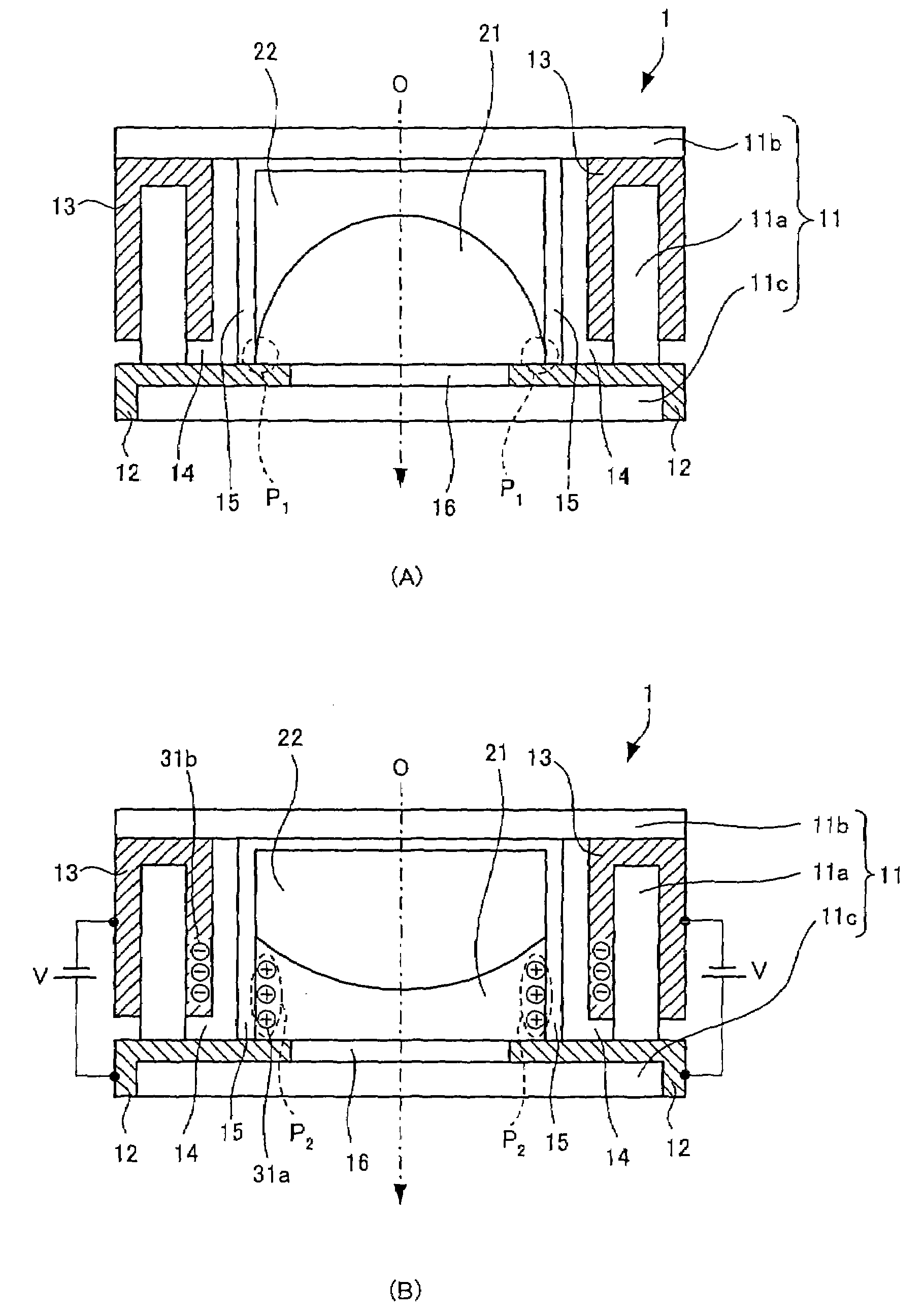
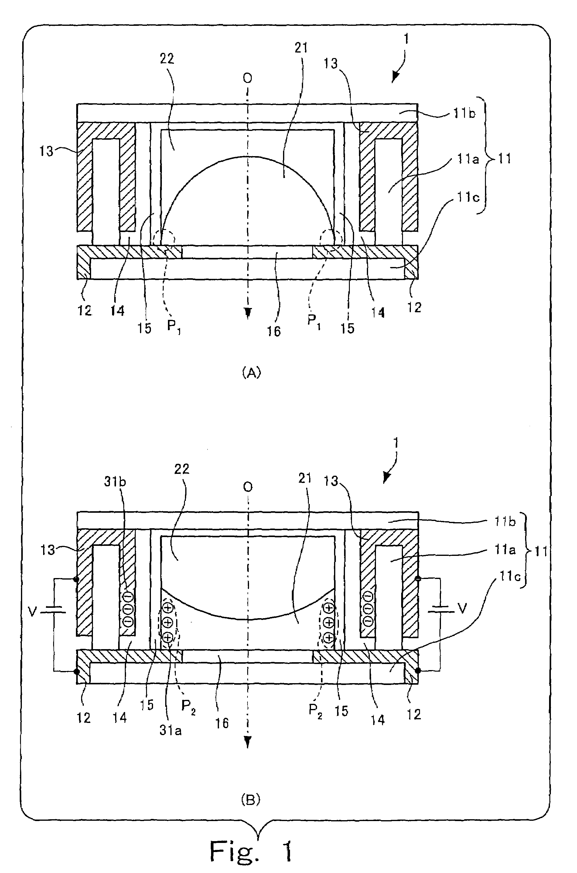
Optical element, lens unit and image pickup apparatus
a technology of optical elements and lens units, applied in the direction of cameras, instruments, printers, etc., can solve the problems of light scattering, light transmission decline, and change of the interface form of two kinds of liquids, so as to maintain light transmission and optical performance.
- Summary
- Abstract
- Description
- Claims
- Application Information
AI Technical Summary
Benefits of technology
Problems solved by technology
Method used
Image
Examples
first embodiment
[0085]This concludes the description of the present invention.
[0086]Here, the optical element of the present invention has an advantage that its optical performance is maintained even in the high temperature environment. A description will be given as to second and third embodiments exploiting this advantage hereunder.
[0087]First, a description will be given as to the second embodiment in which the optical element of the present invention is applied to a monitoring system having a photographic device installed outdoors. As the first embodiment and the second embodiment have approximately the same device configuration, attention is paid to a difference from the first embodiment, and the same elements are given the same symbols to omit a description thereof.
second embodiment
[0088]FIG. 5 is a schematic block diagram of the monitoring system to which the present invention is applied.
[0089]A monitoring system 400 shown in FIG. 5 is configured by connecting a photographic device 410 installed in an outdoor parking lot and so on to a monitoring device 420 installed in an observation room and so on by a network.
[0090]The photographic device 410 obtains various instructions from the monitoring device 420 via a motor driver 120d, and the subject is shot according to the instructions so as to generate digital shot image data. When the shot image data is generated, the voltage applied to the first electrode 202 and the second electrode 203 shown in FIG. 4 is controlled by the focus controller 114a, and the form of the interface between the ionic liquid 301 and the insulating liquid 302 is adjusted to focus on the subject. The generated shot image data is sent to the monitoring device 420.
[0091]The monitoring device 420 performs image processing to the shot image...
third embodiment
[0095]FIG. 6 is a schematic block diagram of the printer to which the present invention is applied.
[0096]A printer 500 has a control section 510 controlling various elements of the printer 500, an image processing section 520 generating the image data representing an output image, a laser emitting section 530 emitting the laser beam based on the image data, a prism 540 refracting the laser beam, and a lens 550 condensing the laser beam on paper 600.
[0097]For instance, the image data obtained by reading an original image is obtained by the image processing section 520, and undergoes predetermined image processing therein. The image data after the image processing is sent to the laser emitting section 530.
[0098]The laser emitting section 530 emits the laser beam based on the image data sent from the image processing section 520. The emitted laser beam is refracted by the prism 540 and gets incident on the lens 550.
[0099]The lens 550 has the same configuration as the focus lens 114 of ...
PUM
| Property | Measurement | Unit |
|---|---|---|
| refractive indices | aaaaa | aaaaa |
| insulating | aaaaa | aaaaa |
| temperature | aaaaa | aaaaa |
Abstract
Description
Claims
Application Information
 - R&D
- Intellectual Property
- Life Sciences
- Materials
- Tech Scout
- Unparalleled Data Quality
- Higher Quality Content
- 60% Fewer Hallucinations
Browse by: Latest US Patents, China's latest patents, Technical Efficacy Thesaurus, Application Domain, Technology Topic, Popular Technical Reports.
© 2025 PatSnap. All rights reserved.Legal|Privacy policy|Modern Slavery Act Transparency Statement|Sitemap|About US| Contact US: help@patsnap.com


