Simulation of aerial images

a technology of aerial images and simulation, applied in the field of photolithography, can solve the problems of complex simulation of aerial images and inability to solve large-scale masks, and achieve the effect of improving computation speed and ease of us

Active Publication Date: 2006-03-02
APPL MATERIALS ISRAEL LTD
View PDF8 Cites 21 Cited by
  • Summary
  • Abstract
  • Description
  • Claims
  • Application Information

AI Technical Summary

Benefits of technology

[0008] Embodiments of the present invention provide improved methods and systems for computing a coherent decomposition of a partially-coherent optical system. The decomposition uses expansion functions, including both radial and angular components, which are expressed in explicit form, thus providing greater ease and speed of computation than OCD methods known in the art. The methods of OCD taught by the present invention are particularly useful in simulating aerial images produced by a projection system, such as the aerial image projected by a photolithographic mask.

Problems solved by technology

Simulation of the aerial image is complicated by the fact that practical lithography systems use partially-coherent illumination.
Although direct computation of this integral is possible, it becomes intractable for large-scale masks.

Method used


Image

  • Simulation of aerial images
  • Simulation of aerial images
  • Simulation of aerial images

Examples


Embodiment Construction

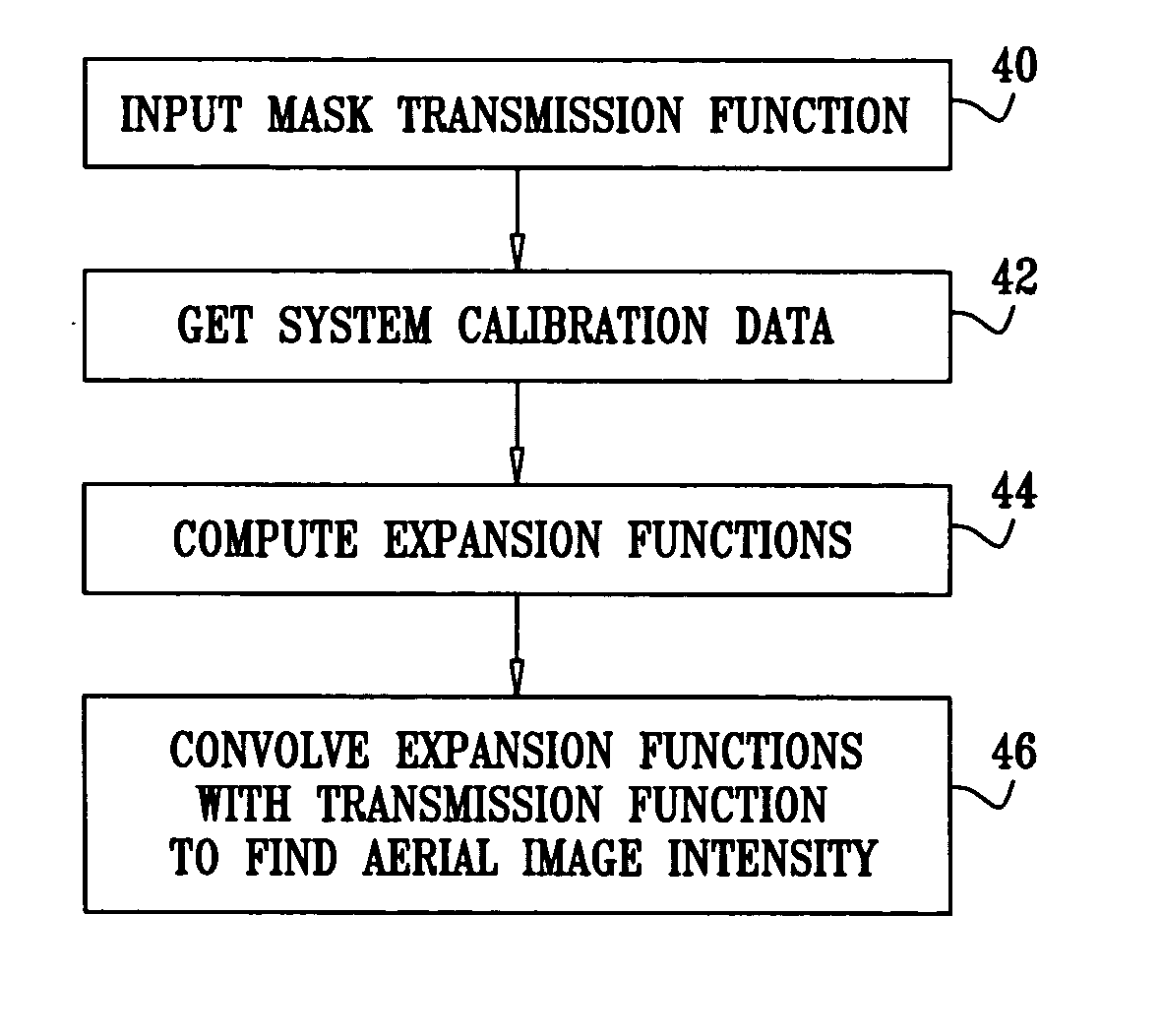
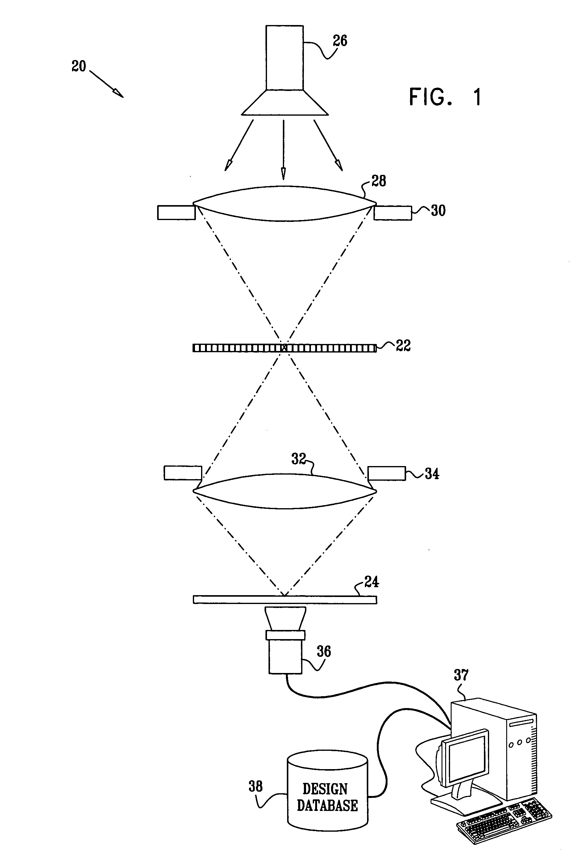
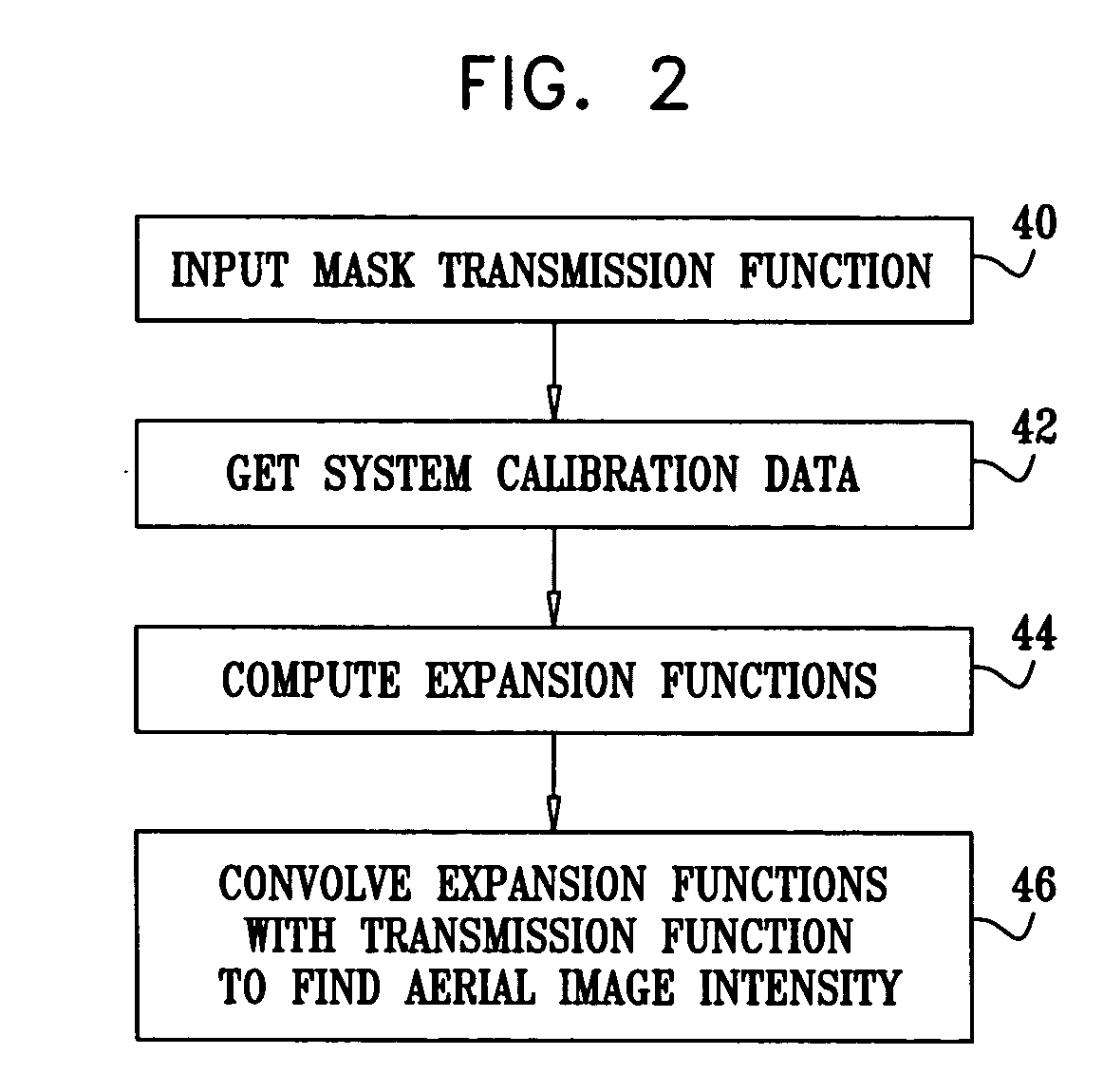
[0057]FIG. 1 is a schematic side view of a system 20 for projection of a mask 22 onto a target plane 24, in accordance with an embodiment of the present invention. Typically, mask 22 embodies a predetermined design for a thin film layer that is to be formed by photolithography on a substrate at plane 24, as is known in the art. The design is characterized by a complex transmission function T({right arrow over (x)}). Alternatively, system 20 may be used in projection of patterns of other types, and the term “mask” should be understood to comprise substantially any sort of object carrying a pattern that can be projected in this manner onto a target plane. Furthermore, the principles of the present invention may also be applied in projection systems that are based on reflection of radiation from mask 22, as well as other types of systems that use optical projection and / or microscopy.

[0058] An illumination source 26 emits radiation, which typically comprises visible, ultraviolet or inf...


PUM


Abstract

A method for generating a simulated aerial image of a mask projected by an optical system includes determining a coherence characteristic of the optical system. A coherent decomposition of the optical system is computed based on the coherence characteristic. The decomposition includes a series of expansion functions having angular and radial components that are expressed as explicit functions. The expansion functions are convolved with a transmission function of the mask in order to generate the simulated aerial image.

Description

CROSS-REFERENCE TO RELATED APPLICATION [0001] This application is related to another U.S. patent application Ser. No. ______, filed on even date, entitled “System and Method for Simulating an Aerial Image,” which is assigned to the assignee of the present patent application and whose disclosure is incorporated herein by reference.FIELD OF THE INVENTION [0002] The present invention relates generally to photolithography, and specifically to simulation of aerial images produced by projecting a mask onto a target surface. BACKGROUND OF THE INVENTION [0003] Photolithography is an essential tool in reproduction of fine patterns on a substrate, and is very widely used in production of microelectronic devices. As the design rules used in such devices become ever finer, mask designers must increasingly resort to reticle enhancement technologies, such as the use of serifs, assist lines and phase shift masks, in order to project the desired pattern onto the device substrate. The aerial image t...

Claims


Application Information

Patent Timeline
Patent Type & Authority Applications(United States)
IPC IPC(8): G06F17/50G21K5/00
CPCG03F1/36G03F7/706G03F7/705G03F1/84
Inventor FELDMAN, HAIM
Owner APPL MATERIALS ISRAEL LTD
Why Eureka
Try Eureka