

Multi-radial shaft for releasable shaft holders
- Summary
- Abstract
- Description
- Claims
- Application Information
AI Technical Summary
Benefits of technology
Problems solved by technology
Method used
Image

Examples
Embodiment Construction
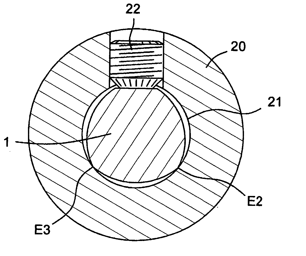
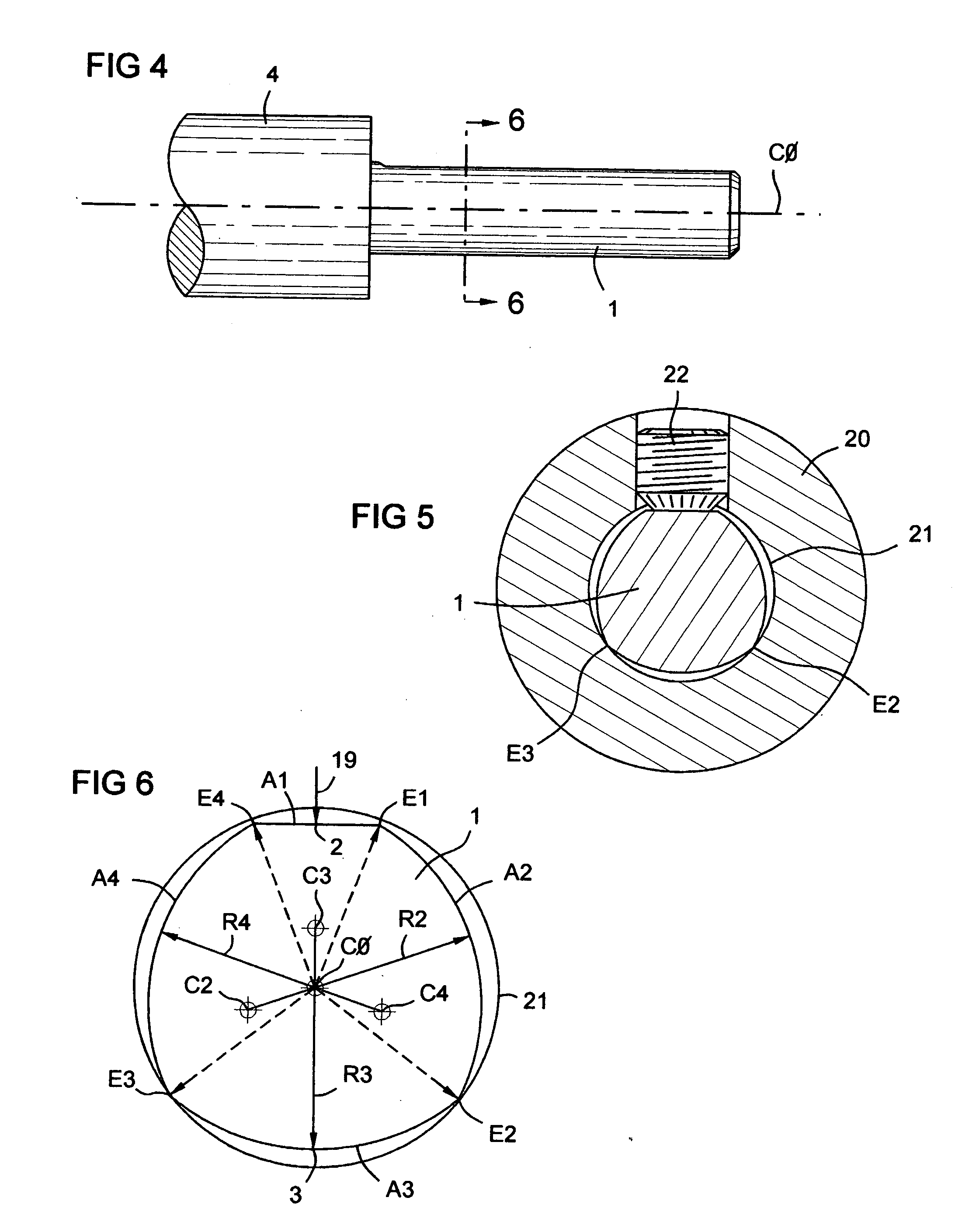
[0073] The invention is a tool shaft 1 for use with a working end 4 of a rotary tool such as a drill, milling cutter, or bore bar, or for use with a stationary tool such as a work-holding arbor or the like. The working end 4 of a rotary tool is driven in rotation about an axis of rotation 2 to perform cutting machining, torque transmission and the like. The shaft is designed to be inserted into, and precisely fixed in, a releasable supporting holder of a drive machine.
[0074] For this purpose the shaft is not cylindrical. It has a cross sectional circumference comprised of a series of arcs A1-A4. The curve A1 can optionally be flat. This segmented circumference extends along the portion of the shaft to be fixed in a holder. The arcs meet sequentially at their end points to form corners or edges E1-E4, two of which, E2 and E3, contact the bore 21 of the holder. A clamping element, such as a set screw 22 in the holder, presses against the midpoint of the first arc A1. This locks the s...
PUM
 Abstract
Description
Claims
Application Information