
Three electrodes system cell for evaluation of performance of molten carbonate fuel cell

a technology of molten carbonate fuel cell and system cell, which is applied in the direction of cell components, fused electrolyte fuel cells, instruments, etc., can solve the problems of lowering the cracking of matrix and electrolyte depletion, and lowering performance of molten carbonate fuel cells. , to achieve the effect of reducing gas leakage, preventing matrix cracking, and reducing adhesive strength

Inactive Publication Date: 2006-03-09
KOREA INST OF SCI & TECH
View PDF2 Cites 6 Cited by
  • Summary
  • Abstract
  • Description
  • Claims
  • Application Information

AI Technical Summary

Benefits of technology

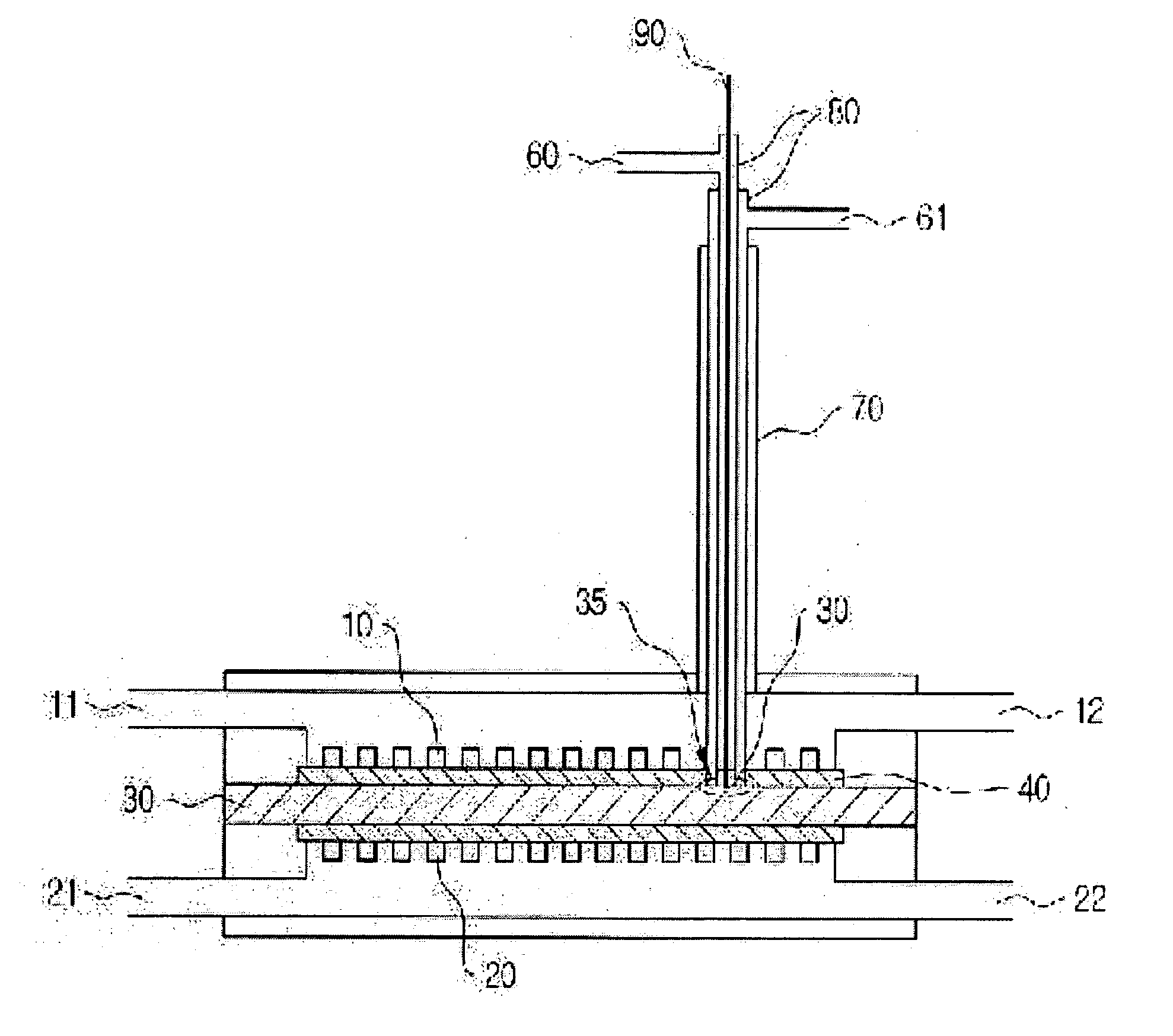
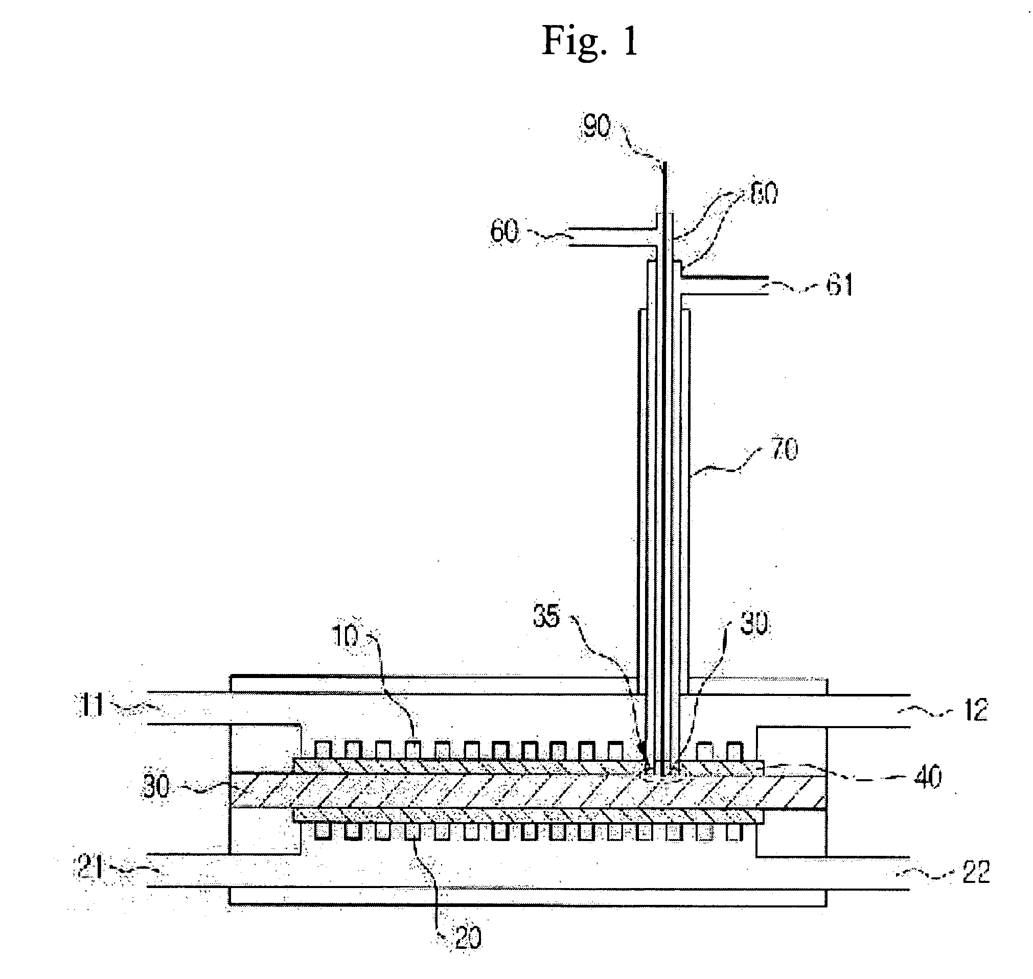
[0028] The second aspect of the object of the invention is to provide an improved three electrodes system cell for evaluation of performance of a molten carbonate fuel cell, capable of preventing a crack of matrix due to a physical shock and a heat shock resulting from outflow and inflow of a supply gas, by changing a mounting position of a reference electrode, contrary to the prior three electrodes system cell.
[0029] The third aspect of the object of the invention is to provide an improved three electrodes system cell for evaluation of performance of a molten carbonate fuel cell, capable of reducing gas leakage resulting from a decrease of adhesive strength between a matrix and an alumina tube and a heat shock due to the gas leakage and improving a problem of electrolyte depletion, by improving the construction of a lower part of a reference electrode, contrary to the prior three electrodes system cell.
[0030] The fourth aspect of the object of the invention is to provide an improved three electrodes system cell for evaluation of performance of a molten carbonate fuel cell, capable of reducing physical defects resulting from a size of a conventional reference electrode, contrary to the prior three electrodes system cell.

Problems solved by technology

However, a long time operation should be possible to commercialize the molten carbonate fuel cell.
Further, a problem of lowering of performance should be settled for the long time operation.
Main factors causing the lowering of performance of the molten carbonate fuel cell are polarization of cathode and anode, cracking of the matrix and the electrolyte depletion.
However, according to the method, there is a problem that it is impossible to separately evaluate the effects of each of factors.
However, in the above method, since the reference electrode penetrates the current collector and the cathode of the single cell, there is voltage swings due to a discharge of the supply gas.
Accordingly, it is impossible to evaluate an exact degree of polarization of an electrode.
However, this method neither can be used to evaluate the long time performance due to the electrolyte depletion.
Instead, the use of the method is limited to an electrochemistry experiment for evaluating the polarization phenomena of the electrodes.

Method used


Image

  • Three electrodes system cell for evaluation of performance of molten carbonate fuel cell
  • Three electrodes system cell for evaluation of performance of molten carbonate fuel cell
  • Three electrodes system cell for evaluation of performance of molten carbonate fuel cell

Examples


Embodiment Construction

[0042] Hereinafter, preferred embodiments of the present invention will be described with reference to the accompanying drawings. In the following description of the present invention, a detailed description of known functions and configurations incorporated herein will be omitted when it may make the subject matter of the present invention rather unclear.

[0043] In the following context, a lower part of a reference electrode is a part of the reference electrode at which the reference electrode and matrix meet, and at which outflows and inflows of electrolyte in the reference electrode and ions in the matrix occur.

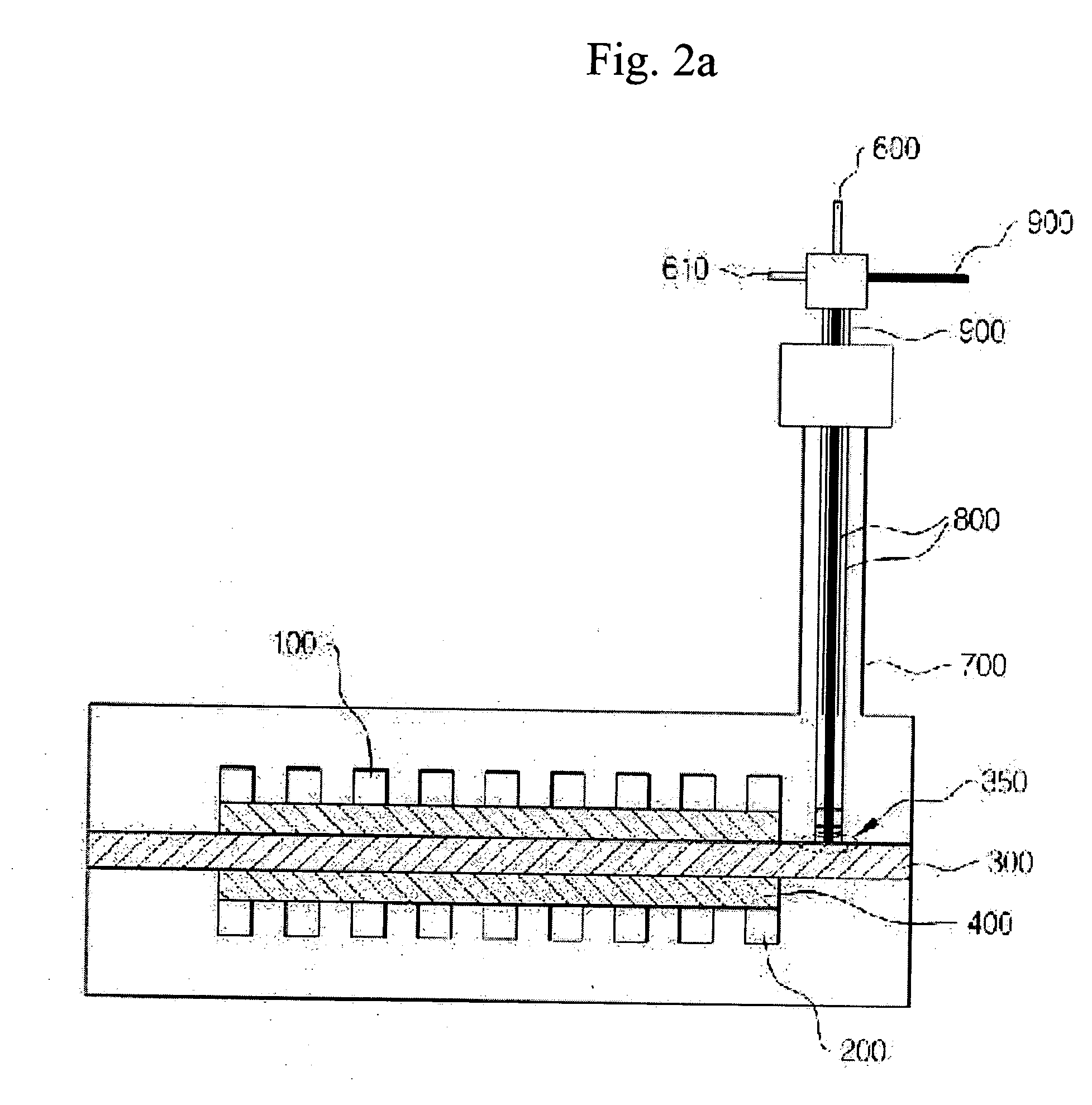
[0044]FIG. 2a is a schematic view showing a structure of a three electrodes system cell according to an embodiment of the invention.

[0045] As shown in FIG. 2a, a reference electrode comprises an alumina tube 800 surrounding and supporting a gold wire 900. The alumina tube 800 of the reference electrode is surrounded and supported by a stainless steel tube 700.

[0046] In ...


PUM

PropertyMeasurementUnit
temperatureaaaaaaaaaa
areaaaaaaaaaaa
areaaaaaaaaaaa

Abstract

Disclosed is a three electrodes system cell for evaluation of performance of a molten carbonate fuel cell. A lower part of the reference electrode is fixed to a wet seal part of the single cell without penetrating a current collector plate and an electrode of the single cell. Preferably, the reference electrode comprises cured matrix slurry and powders of electrolyte stacked on the matrix slurry in the lower part thereof. Preferably, a diameter of an electrolyte-interchanging hole formed in a bottom of the lower part of the reference electrode is 1ψ. Preferably, an outer diameter of an alumina tube in the reference electrode is 6ψ. According to a three electrodes system cell for evaluation of performance of a molten carbonate fuel cell of the invention, it is possible to separately evaluate the performance of each electrode which cannot be evaluated by the prior method of evaluating the performance of the single cell. Particularly, contrary to the prior art, it is possible to prevent a crack of the matrix due to a physical shock and a heat shock resulting from the outflow and inflow of the supply gas, to reduce the gas leakage resulting from a decrease of adhesive strength between the matrix and the alumina tube and a heat shock due to the gas leakage, to improve the problem of electrolyte depletion and to reduce the physical defects resulting from a size of the reference electrode. Accordingly, it is possible to clearly measure the variation of the performance of each electrode while reducing the physical errors to the highest degree, to provide an exact criterion regarding the factor influencing on the variation of performance of the single cell when evaluating the performance of the single cell having 100 cm2 of large area, and to directly evaluate the performance of the molten carbonate fuel cell.

Description

BACKGROUND OF THE INVENTION [0001] 1. Field of the Invention [0002] The present invention relates to an improved three electrodes system cell for evaluation of performance of a molten carbonate fuel cell, particularly to an improved three electrodes system cell for evaluation of performance of a molten carbonate fuel cell capable of evaluating deterioration behaviors of each of factors, which influence on the long-time performance of the molten carbonate fuel cell, as time goes by. [0003] 2. Description of the Related Art [0004] Since the molten carbonate fuel cell (MCFC) is operated at high temperature (for example, 650° C.), it has many advantages as well as merits provided by other fuel cells. [0005] That is, since the MCFC can use high-quality of high temperature exhaust gas, it can be applied to a cogeneration system. In addition, since the MCFC can be operated under pressure, it can be also applied to a combined generation system connected with a gas turbine. [0006] Accordingl...

Claims


Application Information

Patent Timeline
Patent Type & Authority Applications(United States)
IPC IPC(8): G01N27/26H01M8/04
CPCH01M8/04552Y02E60/526H01M2008/147H01M8/14Y02E60/50H01M8/04
Inventor HAN, JONGHEEHONG, SEONG AHNLIM, TAE HOONNAM, SUK-WOOOH, IN HWANYOON, SUNG PILHA, HEUNG YONGCHO, EUNAELEE, JAEYOUNGRYU, BO HYUN
Owner KOREA INST OF SCI & TECH
Learn More