Motor controller and electric power steering apparatus

a technology of motor controller and electric steering apparatus, which is applied in the direction of motor/generator/converter stopper, electronic commutator, dynamo-electric converter control, etc., can solve the problems of torque ripple, vibration, noise, and error between voltage command value and output voltage of pwm inverter

Active Publication Date: 2006-03-09
TOYODA MASCH WORKS LTD +2
View PDF70 Cites 25 Cited by
  • Summary
  • Abstract
  • Description
  • Claims
  • Application Information

AI Technical Summary

Benefits of technology

[0011] Accordingly, it is an objective of the present invention to provide a motor controller and an electric power steering...

Problems solved by technology

However, the dead time causes errors to occur between a voltage command value and an output voltage of the PWM inverter.
This in turn creates torque ripples, vibrations, and current distortion, which can cause sound noise.
When the steering wheel is being turned slowly, that is, when the motor rotates slowly, the torque sensor is likely to pick up current noise.
Particularly, during extreme steering, which causes a large curren...

Method used


Image

  • Motor controller and electric power steering apparatus
  • Motor controller and electric power steering apparatus
  • Motor controller and electric power steering apparatus

Examples


Embodiment Construction

[0028] Hereinafter, an electric power steering (EPS) apparatus according to a preferred embodiment of the present invention will be described with reference to the drawings.

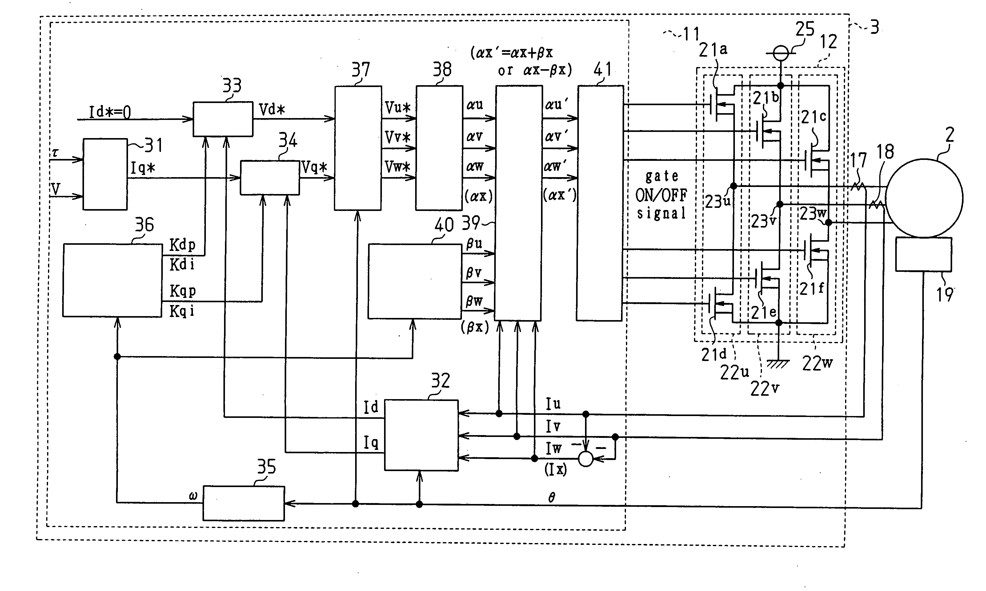
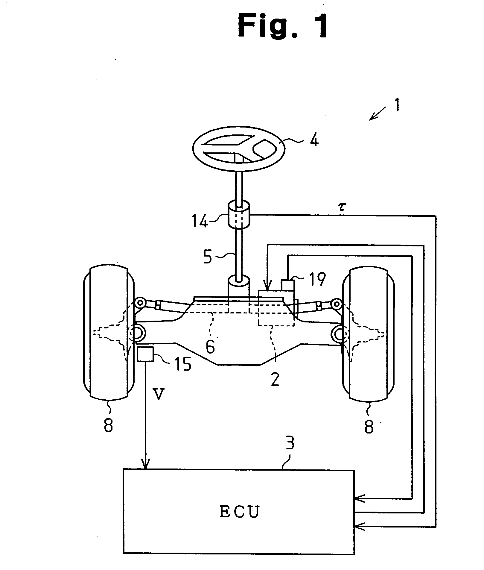
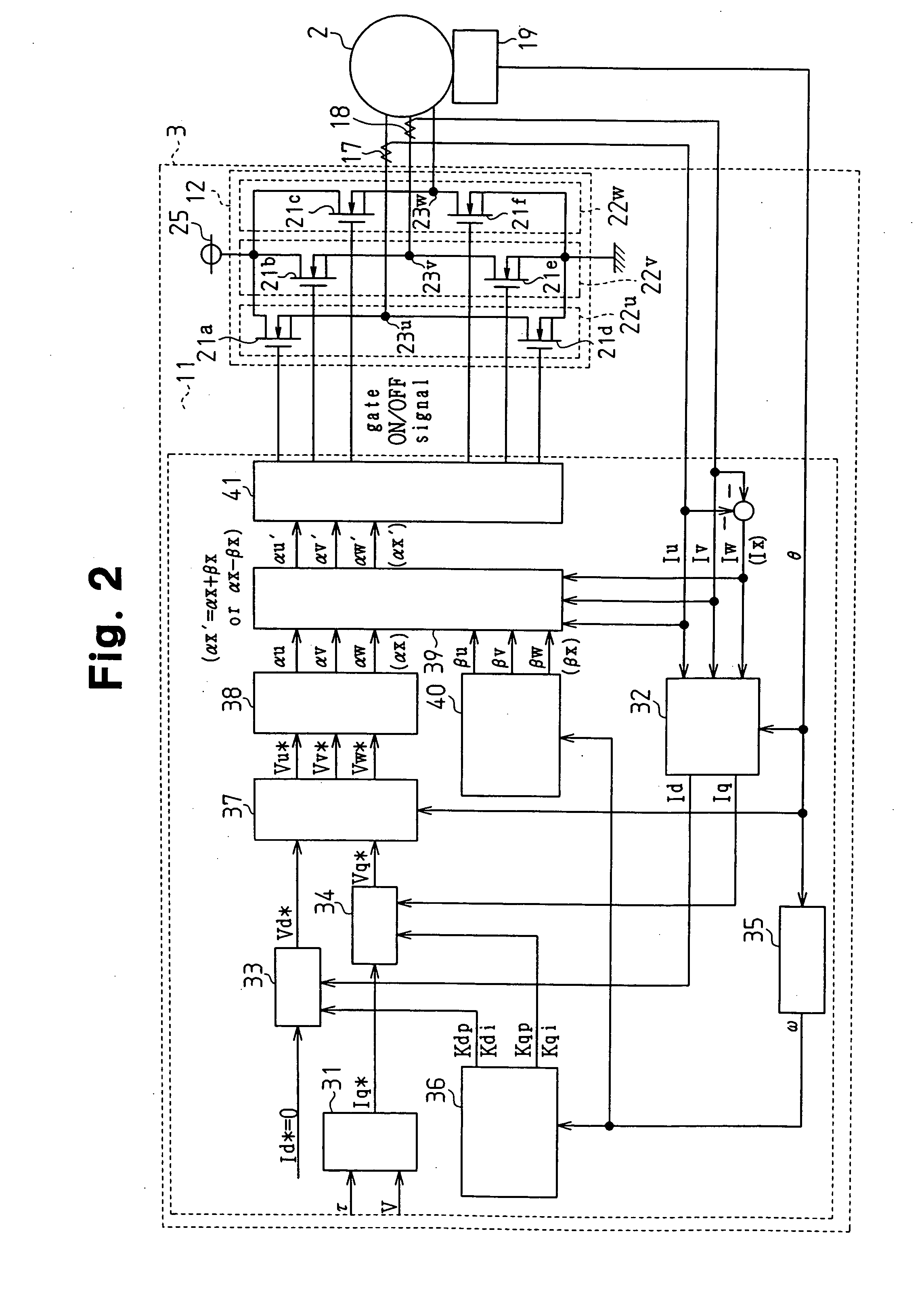
[0029] As shown in FIG. 1, the EPS apparatus 1 includes a brushless motor 2 and an ECU 3. The brushless motor 2 functions as a driving source that applies assisting force to the steering system of a vehicle. The ECU 3 functions as a motor controller that controls the brushless motor 2.

[0030] A steering wheel 4 is coupled to a rack 6 with a steering shaft 5. Rotation of the steering shaft 5 caused by steering operation is converted into linear reciprocation of the rack 6 by means of a rack-and-pinion mechanism (not shown) and is transmitted to steered wheels 8. The EPS apparatus 1 according to this embodiment is a rack type EPS apparatus, in which the brushless motor 2 is arranged coaxial with the rack 6. Assist torque generated by the brushless motor 2 is transmitted to the rack 6 through a ball screw mechanism...


PUM


Abstract

A microcomputer includes a rotation angular velocity computation section, a feedback gain determination section, and a dead time compensation amount determination section. The rotation angular velocity determination section computes the rotation angular velocity of a brushless motor. Based on the rotation angular velocity, the feedback gain determination section determines feedback gains. The dead time compensation amount determination section determines a dead time compensation amount. The greater the absolute value of the rotation angular velocity, that is, the higher the rotation speed of the brushless motor, the greater the feedback gains determined by the feedback gain determination section become, and the higher the responsivity of the feedback gains becomes. The greater the absolute value of the rotation angular velocity, the smaller the dead time compensation amount determined by the dead time compensation amount determination section becomes.

Description

BACKGROUND OF THE INVENTION [0001] The present invention relates to a motor controller and an electric power steering apparatus. [0002] Conventionally, a type of a motor controller has been used which converts direct-current voltage supplied from a direct-current power supply to three-phase (U, V, W) drive power using a PWM (pulse-width modulation) inverter, and supplies the three-phase drive power to a brushless motor. [0003] As shown in FIG. 7, a PWM inventor is configured of three arms 52 in parallel as basic units. Each arm 52 corresponds to one of the phases and includes a pair of switching elements (for example, power MOSFETs) 51a, 51b in series. The motor controller alternately turns on and off the high voltage side switching element 51a and the low voltage side switching element 51b of each arm 52 at a predetermined timing, thereby supplying three-phase drive power to a brushless motor 53. [0004] In such a motor controller, to prevent a short circuit (arm short circuit) betw...

Claims


Application Information

Patent Timeline
IPC IPC(8): H02P7/42B62D5/04H02P5/00H02P6/06H02P6/08H02P6/17H02P6/28
CPCB62D5/046H02M2001/385H02M7/53875H02M1/385
Inventor SUZUKI, HIROSHI
Owner TOYODA MASCH WORKS LTD
Why Eureka
Try Eureka