

Magnetic resonance imaging device
- Summary
- Abstract
- Description
- Claims
- Application Information
AI Technical Summary
Benefits of technology
Problems solved by technology
Method used
Image

Examples
first embodiment
[0020] Hereinafter, an MRI apparatus and an MR imaging method according to the present invention will be described with reference to the drawings. First, a first embodiment of the MRI apparatus according to the present invention will be described with reference to FIG. 1 to FIG. 7.
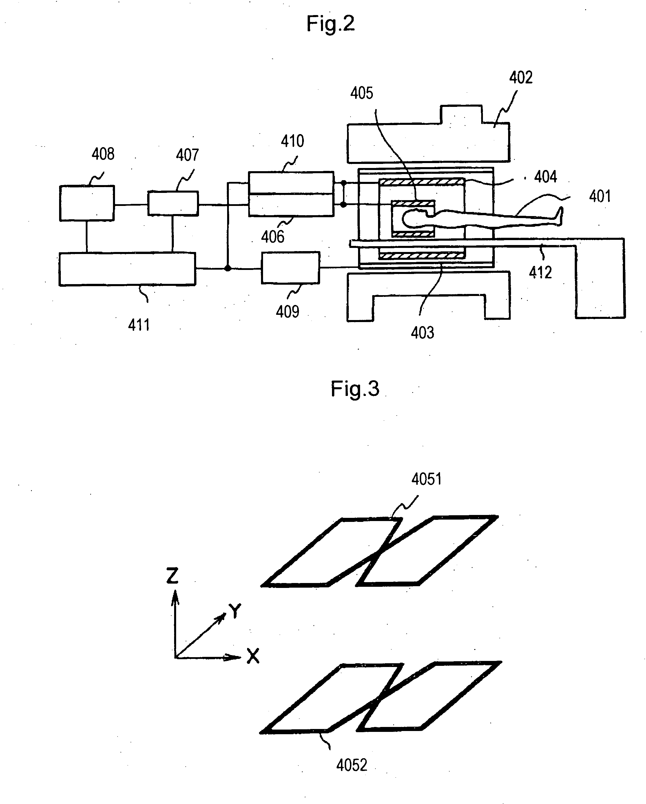
[0021] As shown in FIG. 2, the MRI apparatus according to this embodiment includes magnet 402 for generating a uniform static magnetic field having a predetermined strength to a space (hereinafter referred to as “imaging space”) having a predetermined size for accommodating object 401 to be examined, gradient magnetic field coil 403 for generating gradient magnetic fields to the imaging space, body coil 404 for generating a radio-frequency magnetic field to the imaging space and detecting an NMR signal generated by object 401, and RF probe 405 for detecting the NMR signal generated by object 401. Here and hereinafter, “RF” is an abbreviation of “Radio Frequency.” Although FIG. 2 shows an MRI apparatus of ...
second embodiment
[0063] Second embodiment of MRI apparatus according to the present invention will be described with reference to FIG. 8 and FIG. 9. Because the same functions as in the first embodiment are given the same reference marks, only the difference with the first embodiment will be hereinafter described.
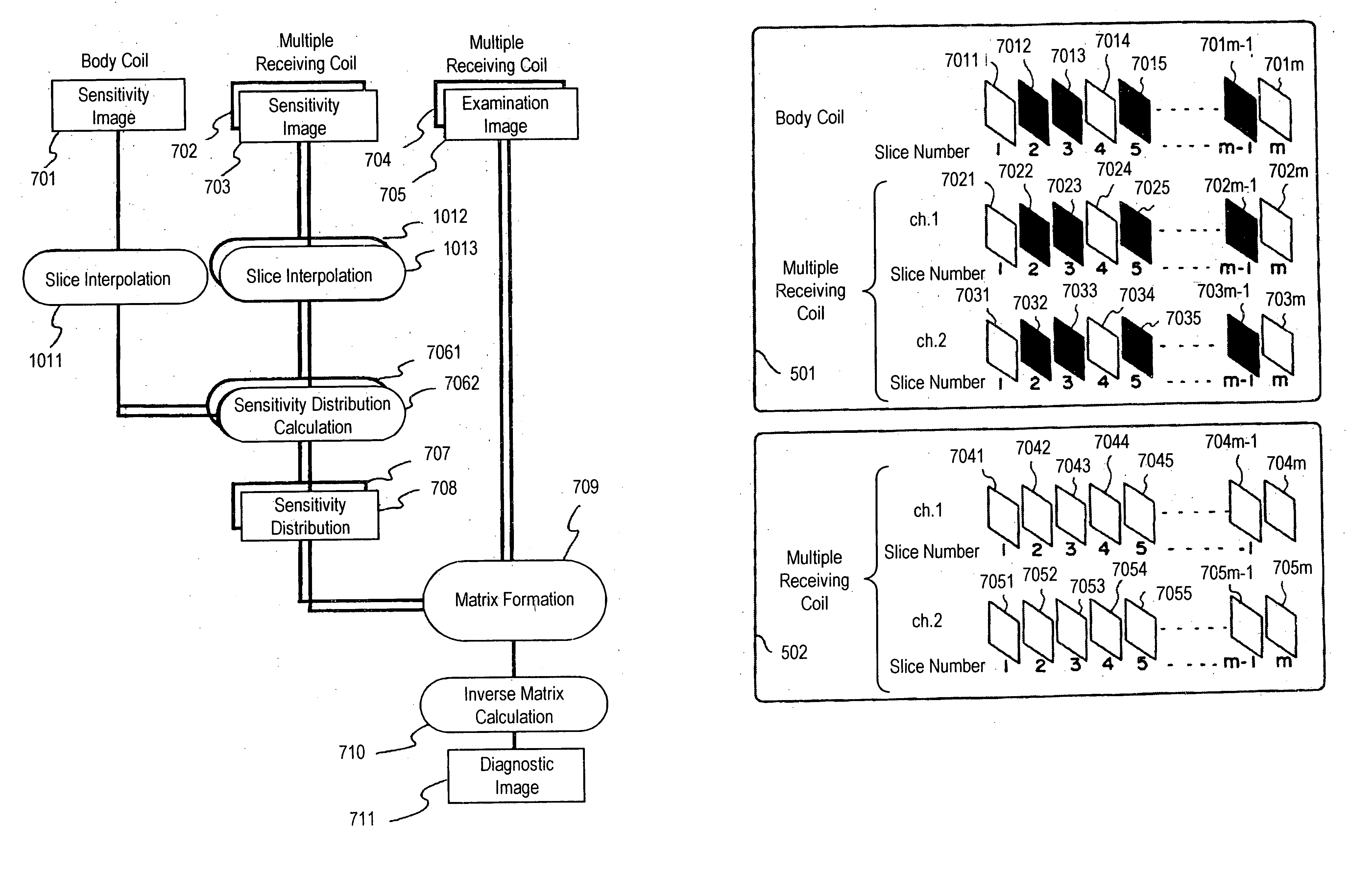
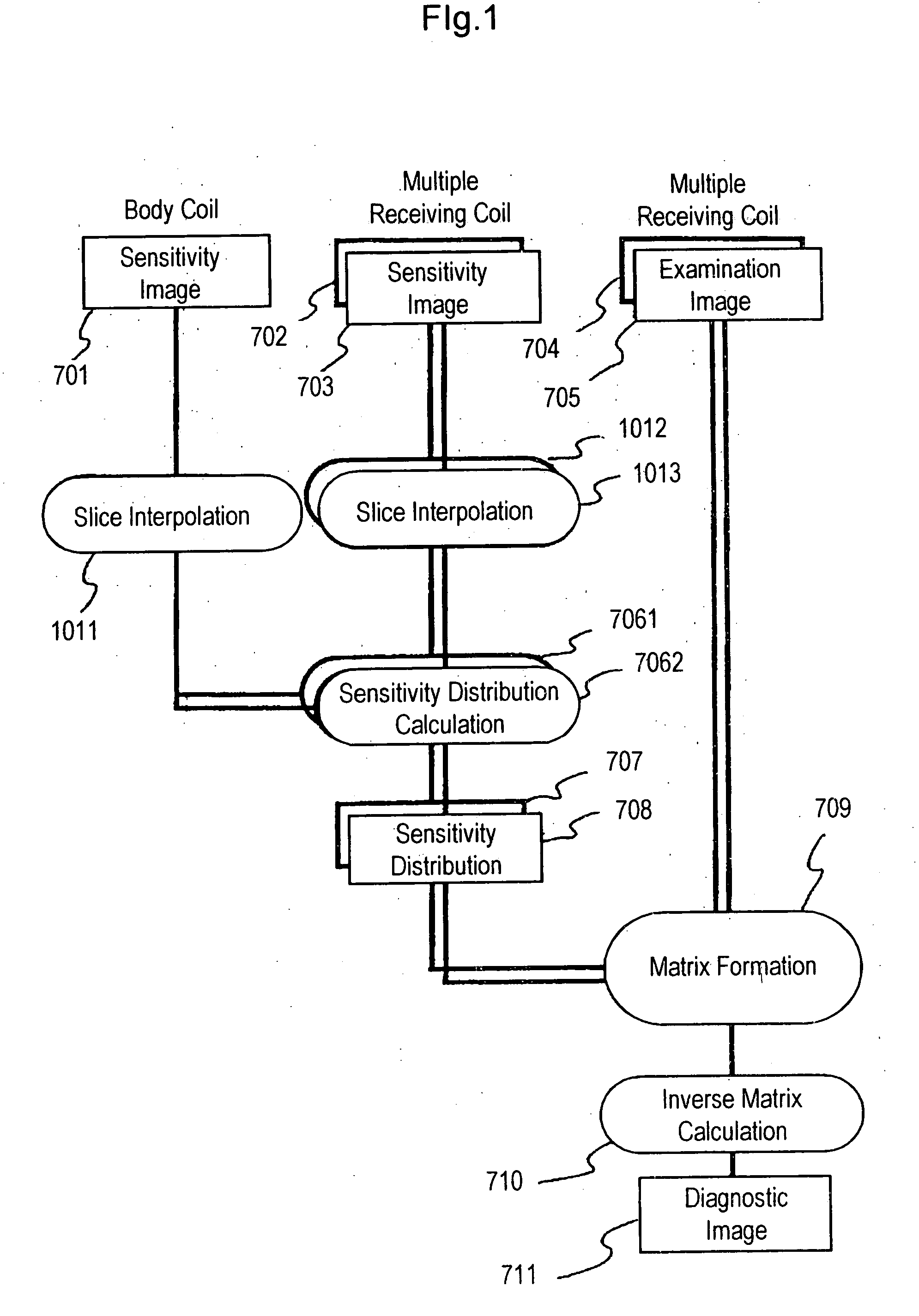
[0064] The difference between this embodiment and the first embodiment is, as shown in FIG. 8, that slice interpolation processing 801 is performed after sensitivity distribution calculation processing 706 is performed using sensitivity image 701 of body coil 404 and sensitivity images 702 and 703 of receiving coils 705.1 and 4052 of multiple receiving coils 301 acquired in the pre-measurement pulse sequence for the sensitivity image data acquisition. Therefore, in the signal processing unit according to this embodiment, sensitivity distribution data 7061 and 7062 of receiving coils 4051 and 4052 are calculated from sensitivity image 701 of body coil 404 and sensitivity images 702 and 703 ...
third embodiment
[0072] Next, the third embodiment of MRI apparatus according to the present invention will be described with reference to FIG. 10 and FIG. 11. Meanwhile, in this embodiment, too, the same function as in First embodiment is given the same reference mark and the description thereof will be omitted. The structure different from First embodiment and the characteristic part will be described hereinafter.
[0073] The difference between this embodiment and First embodiment lies in that the multiple receiving coils include four receiving coils. That is, as shown in FIG. 10, multiple receiving coils 301A forming an RF probe in the MRI apparatus according to this embodiment include four figure-of-eight shaped receiving coils 4051 to 4054, which are arranged opposite on the X-Y plane and on the T-Z plane at a predetermined distance.
[0074] Further, as shown in FIG. 11, four receiving coils 4051 to 4054 of multiple RF receiving coils 301A according to this embodiment are respectively connected t...
PUM
 Abstract
Description
Claims
Application Information