Organic electroluminescent element
a technology of electroluminescent elements and organic elements, which is applied in the direction of luminescnet screens of discharge tubes, natural mineral layered products, transportation and packaging, etc., can solve the problems of deteriorating inability to raise luminous efficiency, and large injection barrier thereto, so as to reduce driving voltage and improve luminous efficiency , the effect of improving the balance of electrons and holes
- Summary
- Abstract
- Description
- Claims
- Application Information
AI Technical Summary
Benefits of technology
Problems solved by technology
Method used
Image
Examples
examples 8 and 9
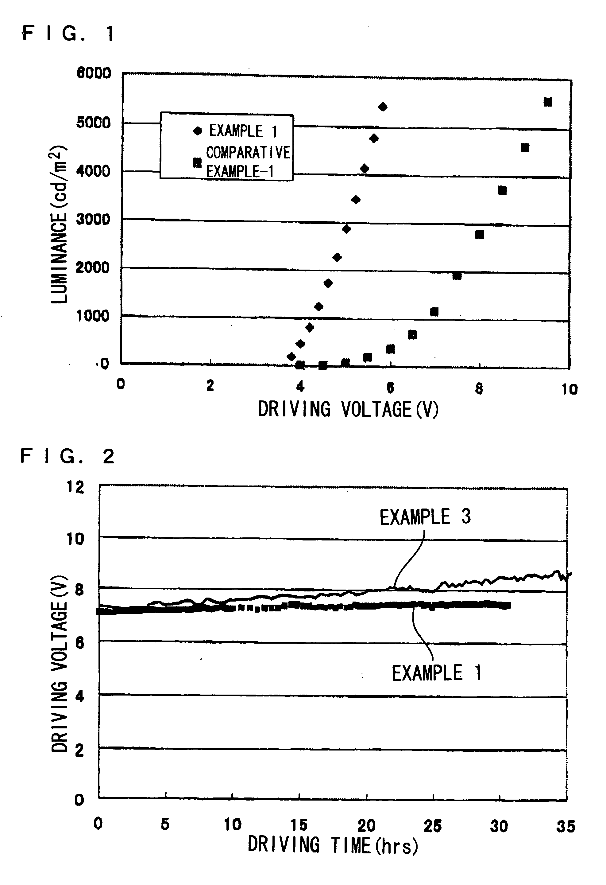
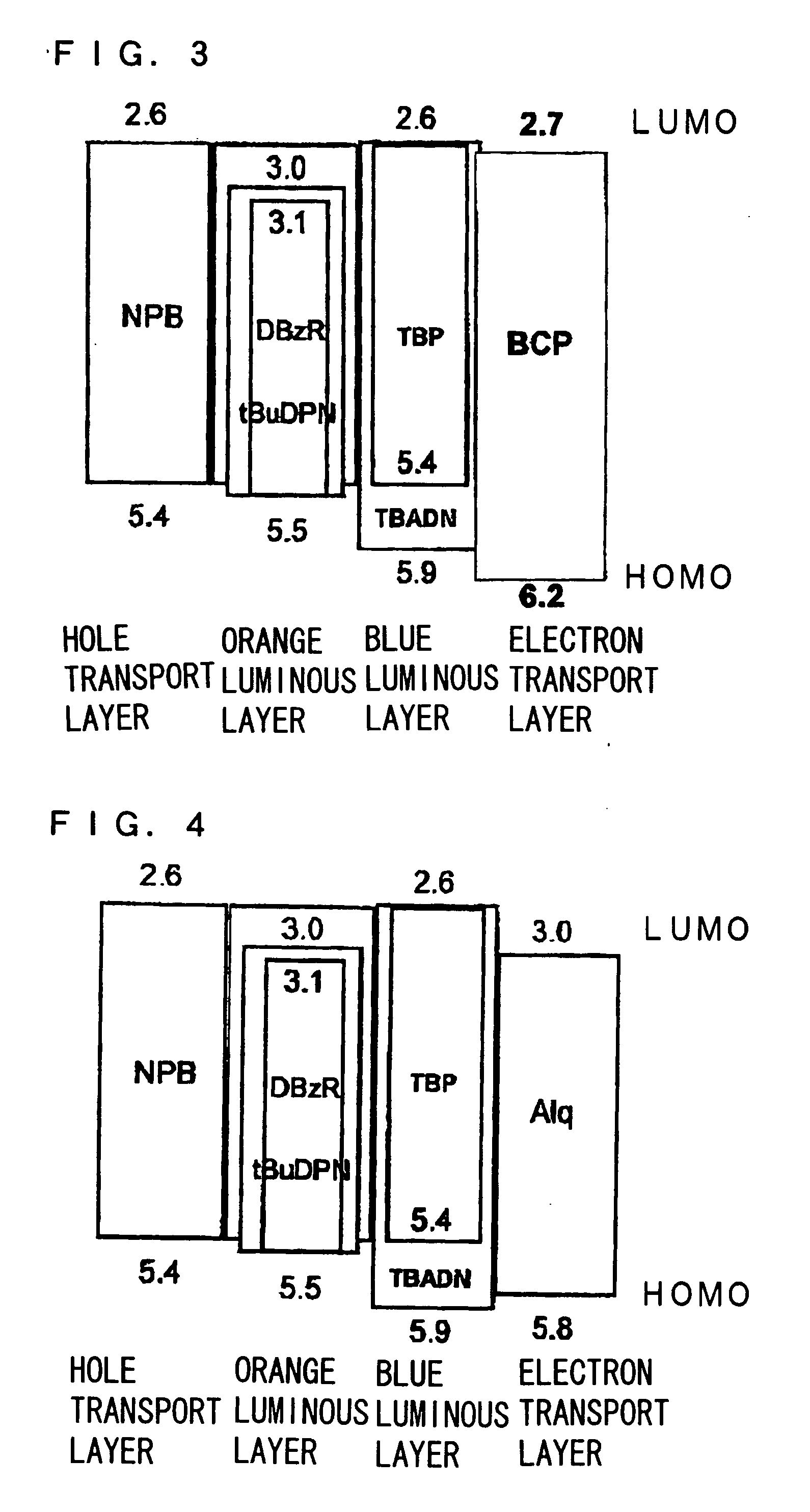
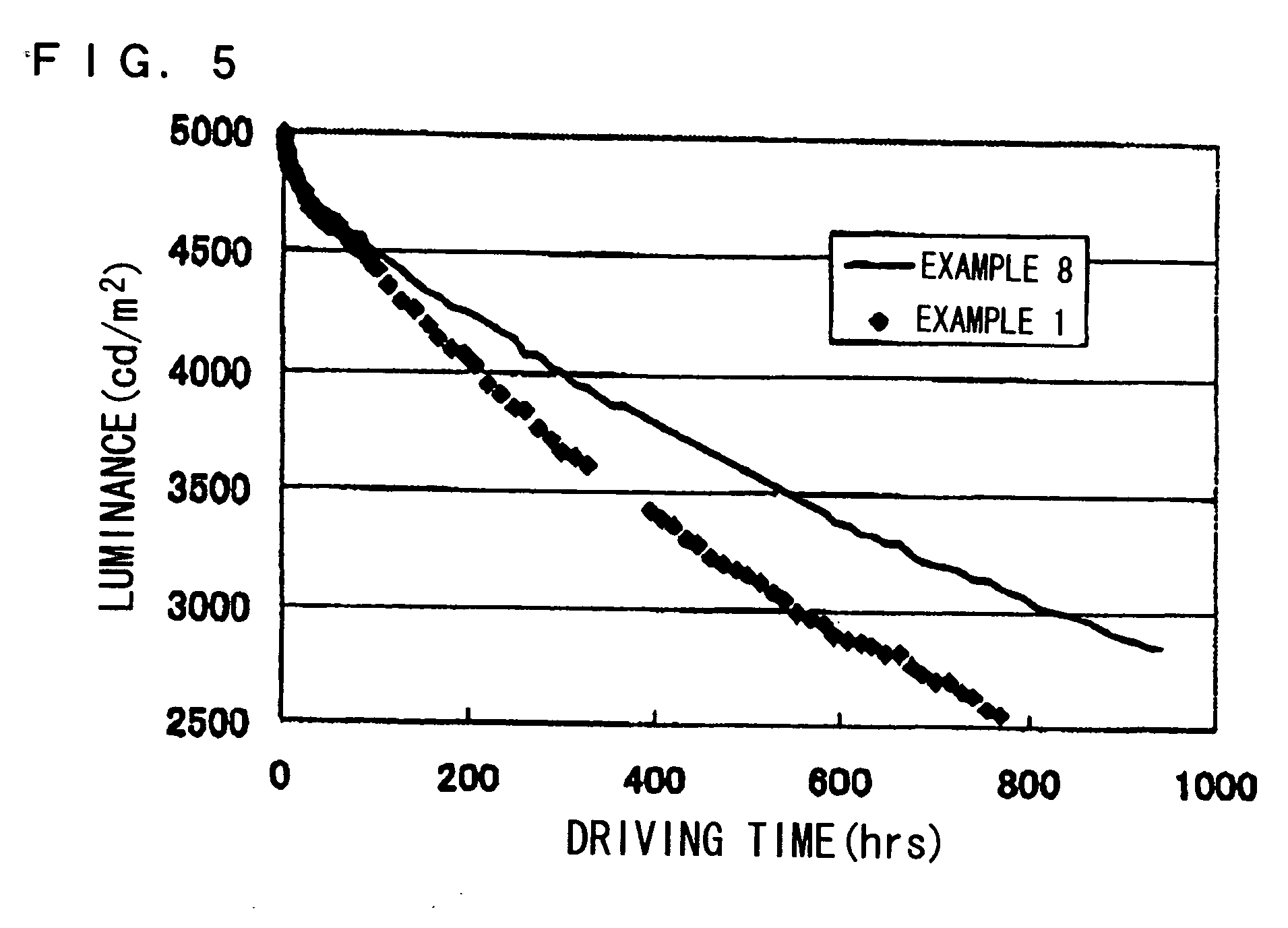
[0076] A hole injection layer, a fluorocarbon layer, a hole transport layer, a light emitting layer 1 (an orange light emitting layer), a light emitting layer 2 (a blue light emitting layer), an electron transport layer and an electron injection electrode (LiF / Al) shown in Table 3 were formed on a glass substrate on which an ITO (indium-tin oxide) film was formed as a hole injection electrode. In Table 3, the numbers in parentheses denote the thickness (nm) of each of the layers. The fluorocarbon layer was formed by plasma polymerization of CHF3 gas. Each of the layers except the fluorocarbon layer was formed by vapor deposition process. In Table 3, the numerical values of LiF and Al denote the thickness of the layers. % in the light emitting layer and the electron transport layer denotes weight %.
[0077] With regard to each organic EL element manufactured, chromaticity, electric power efficiency, luminance efficiency, external quantum efficiency and luminance half-value time were m...
examples 10 to 13
[0078] In the same manner as the above-mentioned Examples, each layer shown in Table 4 was formed on a glass substrate, on which an ITO film was formed, to manufacture organic EL elements. With regard to each of the elements, chromaticity, electric power efficiency, luminance efficiency, external quantum efficiency and luminance half-value time were measured to show the results in Table 4. Examples 4 to 7 are shown together in Table 4.
TABLE 4HoleFluoro-HoleElectronLuminescentInjectioncarbonTransportLuminousTransportColorLayerLayerLayerLayerLayerExampleBlueCuPCCFxNPBTBADN + 2%BCP + 20%10(100)(10)(1500)TBPAlq(400)(100)Example 4BlueCuPCCFxNPBTBADN + 2%BCP(100)(10)(1500)TBP(100)(400)ExampleOrangeCuPCCFxNPBNPB + 3%BCP + 20%11(100)(10)(1500)DBzRAlq(400)(100)Example 5OrangeCuPCCFxNPBNPB + 3%BCP(100)(10)(1500)DBzR(100)(400)ExampleGreenCuPCCFxNPBNPB + tBUDPNBCP + 20%12(100)(10)(1500)(400)Alq(100)Example 6GreenCuPCCFxNPBNPB + tBuDPNBCP(100)(10)(1500)(400)(100)ExampleRedCuPCCFxNPBAlq + 3%BCP...
PUM
| Property | Measurement | Unit |
|---|---|---|
| Percent by mass | aaaaa | aaaaa |
| Percent by mass | aaaaa | aaaaa |
| Energy level | aaaaa | aaaaa |
Abstract
Description
Claims
Application Information
 - R&D
- Intellectual Property
- Life Sciences
- Materials
- Tech Scout
- Unparalleled Data Quality
- Higher Quality Content
- 60% Fewer Hallucinations
Browse by: Latest US Patents, China's latest patents, Technical Efficacy Thesaurus, Application Domain, Technology Topic, Popular Technical Reports.
© 2025 PatSnap. All rights reserved.Legal|Privacy policy|Modern Slavery Act Transparency Statement|Sitemap|About US| Contact US: help@patsnap.com


