
Packet communication network, route control server, route control method, packet transmission device, admission control server, light wavelength path setting method, program, and recording medium

a packet communication network and routing control technology, applied in the field of routing control techniques of packet communication networks, can solve the problems of high cost of acquiring optical wavelength path resources, limited capacity of backbone networks, and explosive growth of large-scale backbone networks at the center of the internet, so as to ensure end-to-end communication quality, network carrying efficiency may decrease, and network resources can be used more efficiently

Inactive Publication Date: 2006-03-09
NIPPON TELEGRAPH & TELEPHONE CORP
View PDF2 Cites 20 Cited by
  • Summary
  • Abstract
  • Description
  • Claims
  • Application Information

AI Technical Summary

Benefits of technology

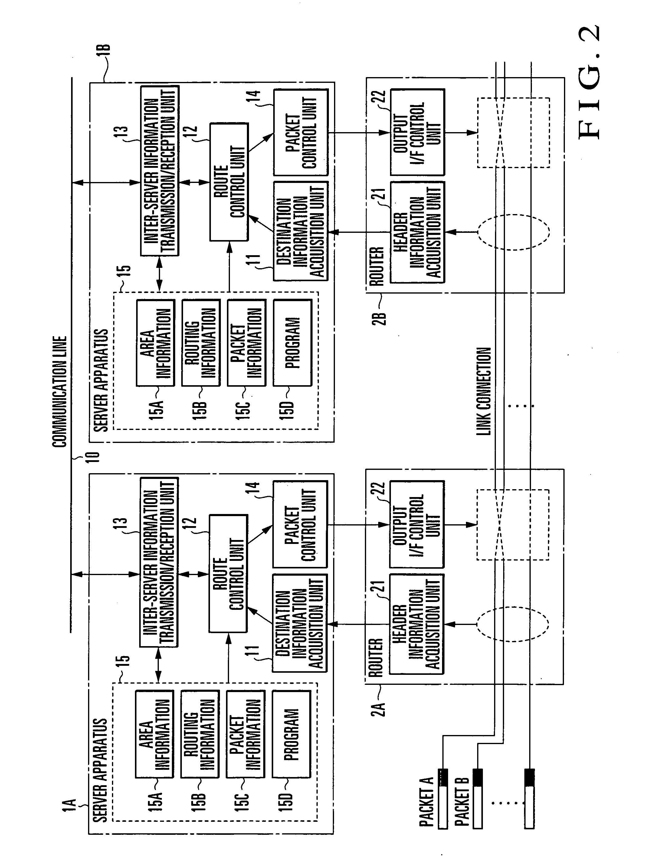
[0021] According to the present invention, the route control server to manage the router in each area can execute route control based on transfer management information for a packet having destination information on the basis of inter-server information sent from another route control server. Hence, even for a packet which passes through a plurality of areas managed by different route control servers, packet transfer control can unitedly be done by the route management route control servers so that appropriate route control can be implemented in the entire network.
[0022] When the route control servers which manage the areas execute route control independently, the network carrying efficiency may decrease due to disunity of packet management control in some areas, or the network load may be unbalanced by packet concentration to a boundary router that connects the areas. However, these problems can be avoided, and the network resources can be used more efficiently.
[0023] In setting a path with an explicitly designated communication quality between routers, even when a packet passes through areas controlled by a plurality of route control servers, an end-to-end communication quality can be ensured.
[0024] According to the present invention, an optical wavelength path which can exclusively be used by the user is set between specific user terminals, i.e., the packet transfer apparatuses of transmission source and destination in accordance with a band guarantee request from the user while utilizing the existing photonic network. For this reason, the communication capacity can flexibly be expanded, and a band-guarantee-type network service can be provided.
[0025] When no band guarantee request is present, an optical wavelength path which passes through the frame transfer apparatus is set between the packet transfer apparatuses of the transmission source and destination. Since the transfer resources of IP transfer routes are shared, the cost of transfer resource acquisition can be reduced while ensuring reachability of communication. In addition, scalability can be increased.

Problems solved by technology

As the number of Internet users rapidly increases and applications to transmit mass storage data quickly become popular, the traffic amount of a large-scale backbone network at the center of the Internet is explosively increasing.
However, the backbone network has only a limited capacity, like a general communication network.
In such a photonic network, when packet transfer apparatuses which accommodate subscriber users are permanently connected by an optical wavelength path, the cost of acquiring an optical wavelength path resource is high.
In addition, the system is poor in scalability.

Method used


Image

  • Packet communication network, route control server, route control method, packet transmission device, admission control server, light wavelength path setting method, program, and recording medium
  • Packet communication network, route control server, route control method, packet transmission device, admission control server, light wavelength path setting method, program, and recording medium
  • Packet communication network, route control server, route control method, packet transmission device, admission control server, light wavelength path setting method, program, and recording medium

Examples


first embodiment

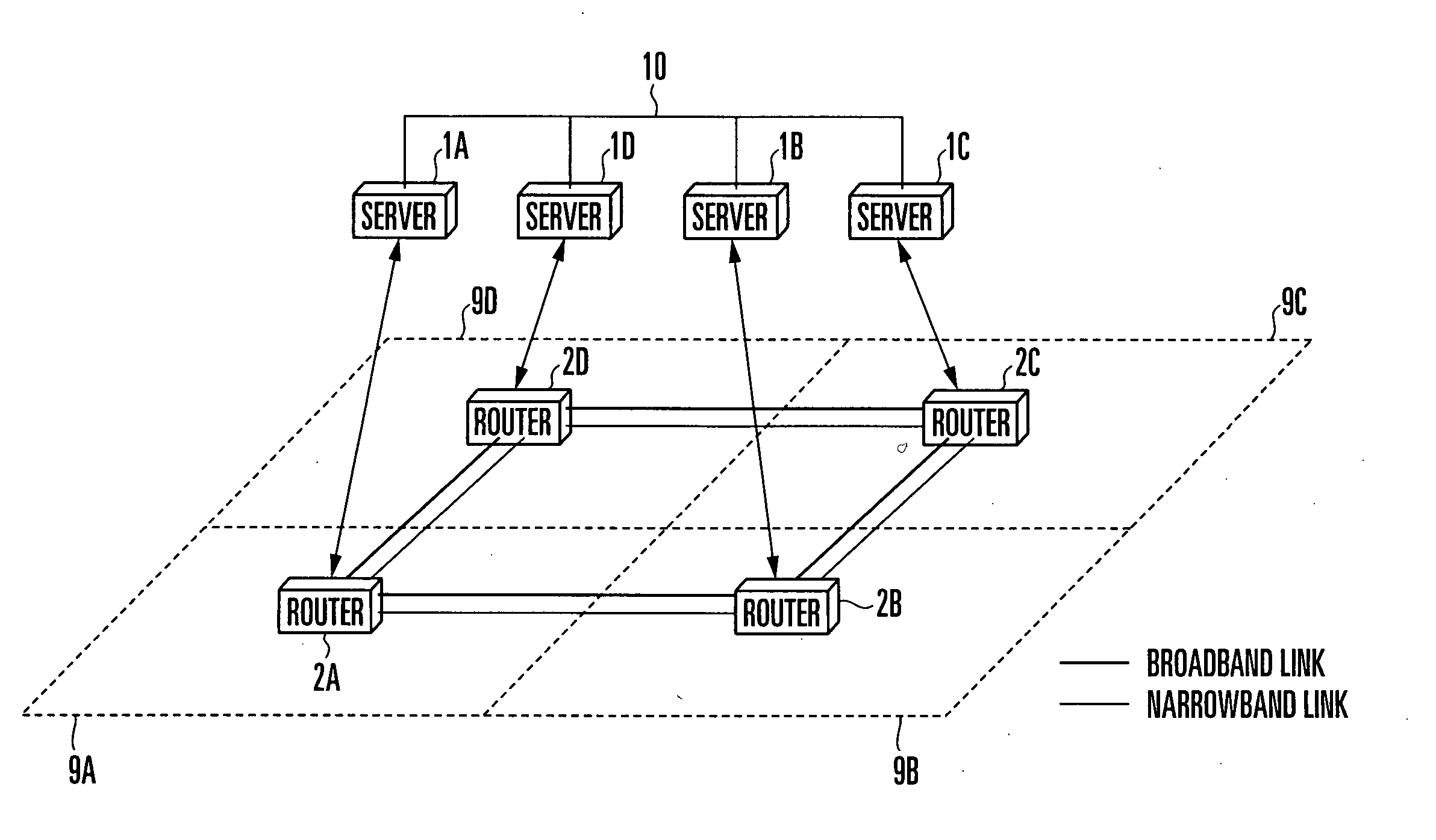
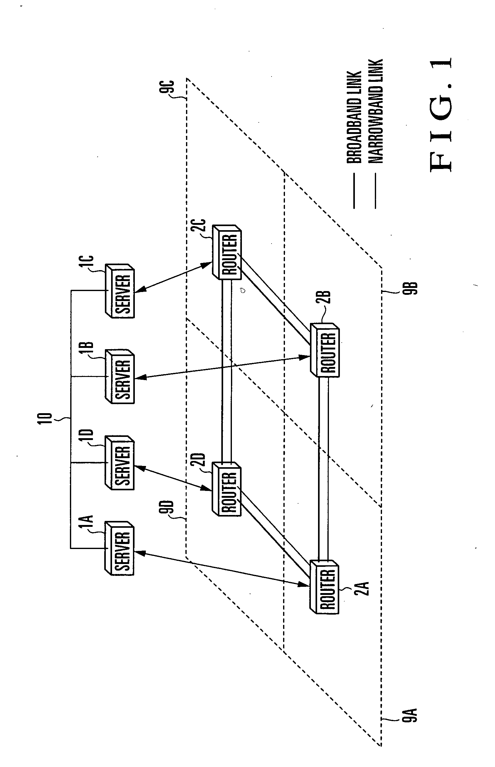
[0047] A packet communication network to which a route control server and router according to the first embodiment of the present invention are applied will be described with reference to FIG. 1. FIG. 1 is a block diagram showing the arrangement of a packet communication system to which a route control server and router according to the first embodiment of the present invention are applied.

[0048] The packet communication network includes a plurality of route control servers 1 (1A, 1B, 1C, and 1D) and a plurality of routers 2 (2A, 2B, 2C, and 2D).

[0049] The route control server 1 is formed from a route control server apparatus implemented by a computer as a whole. The route control server is a control apparatus to determine the transfer destination route of a packet, which has arrived at the router 2, on the basis of its header information.

[0050] The router 2 is connected to the remaining routers through communication links and, in this case, broadband communication links or narro...

second embodiment

[0100] A communication network according to the second embodiment of the present invention will be described with reference to FIG. 11. FIG. 11 is a block diagram showing the network model of the communication network according to the second embodiment of the present invention.

[0101] This communication network assumes a photonic network 8A as a connection network and an IPv4 in IPv6 network 8 as a connectionless network.

[0102] The photonic network 8A employs a wavelength switch as a connection switching device. In the IPv4 in IPv6 network 8, the lower layer includes an IPv6 network 9. An IPv6 frame is applied as the lower layer frame. The upper layer includes an IPv4 network 8B. An IPv4 packet is applied as the upper layer packet. The IPv6 network 9 corresponds to the cell 9 (9A to 9D) in the first embodiment.

[0103] In the communication network shown in FIG. 11, packet transfer apparatuses 3 (3A, 3B, 3C, and 3D), frame transfer apparatus 2, wavelength switches 5A and 5B, and admi...


PUM


Abstract

A route control server (1) sends destination information acquired by a router (2) in a managed area and transfer management information corresponding to the destination information to another route control server and determines the output interface of a packet on the basis of the destination information and transfer management information. A packet transfer apparatus (3) executes mutual conversion and transfer of an upper layer packet on a user terminal side and a lower layer frame on an optical wavelength path side. An admission control server (4) sets, of the optical wavelength paths of the photonic network, an optical wavelength path formed from a cut-through optical wavelength path which has a guaranteed band and directly connects packet transfer apparatuses of transmission source and destination in accordance with an optical wavelength path connection request from a transmission source user terminal.

Description

TECHNICAL FIELD [0001] The present invention relates to a route control technique of a packet communication network and, more particularly, to a route control technique of setting a desired route by controlling routers and packet transfer apparatuses included in a large-scale network such as a photonic network. BACKGROUND ART [0002] As the number of Internet users rapidly increases and applications to transmit mass storage data quickly become popular, the traffic amount of a large-scale backbone network at the center of the Internet is explosively increasing. [0003] However, the backbone network has only a limited capacity, like a general communication network. Hence, to increase the traffic amount of the backbone network as much as possible, appropriate route control must be done in the entire network. [0004] Conventionally, a route control method for a general communication network is proposed in which one route control server is arranged for a target network to collectively manag...

Claims


Application Information

Patent Timeline
IPC IPC(8): G06F15/173H04L12/56
CPCH04L45/42H04L45/00
Inventor MATSUI, KENICHIYAGI, TAKESHINARUSE, YUUICHIMURAYAMA, JUNICHI
Owner NIPPON TELEGRAPH & TELEPHONE CORP
Learn More