Heat pump with reheat and economizer functions

a heat pump and function technology, applied in the field of heat pump refrigerant systems, can solve the problems of unincorporated combination and selective operation of reheat coil and economizer cycle, design challenges of refrigerant cycle designers, and inability to fully develop variations of this basic concept, etc., to achieve the effect of improving system control and broader application coverage, improving comfort, and improving the performance of heat pump systems

Inactive Publication Date: 2006-03-16
CARRIER CORP
View PDF23 Cites 41 Cited by
  • Summary
  • Abstract
  • Description
  • Claims
  • Application Information

AI Technical Summary

Benefits of technology

[0009] In addition, the reheat coil can be operable in combination with an economizer circuit. The economizer circuit augments the performance of the heat pump system in a heating mode and in a variety of cooling modes of operation. The combinat

Problems solved by technology

Furthermore, if the expansion device cannot handle the reversed flow, then a pair of unidirectional expansion devices, each along with the corresponding check valve, is to be employed instead.
This has presented design challenges to refrigerant cycle de

Method used


Image

  • Heat pump with reheat and economizer functions
  • Heat pump with reheat and economizer functions
  • Heat pump with reheat and economizer functions

Examples


Embodiment Construction

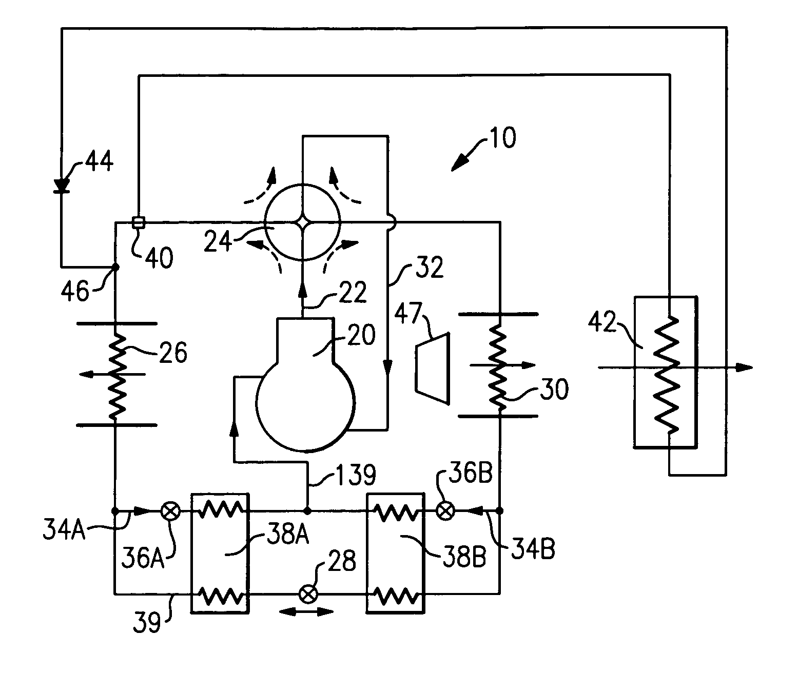
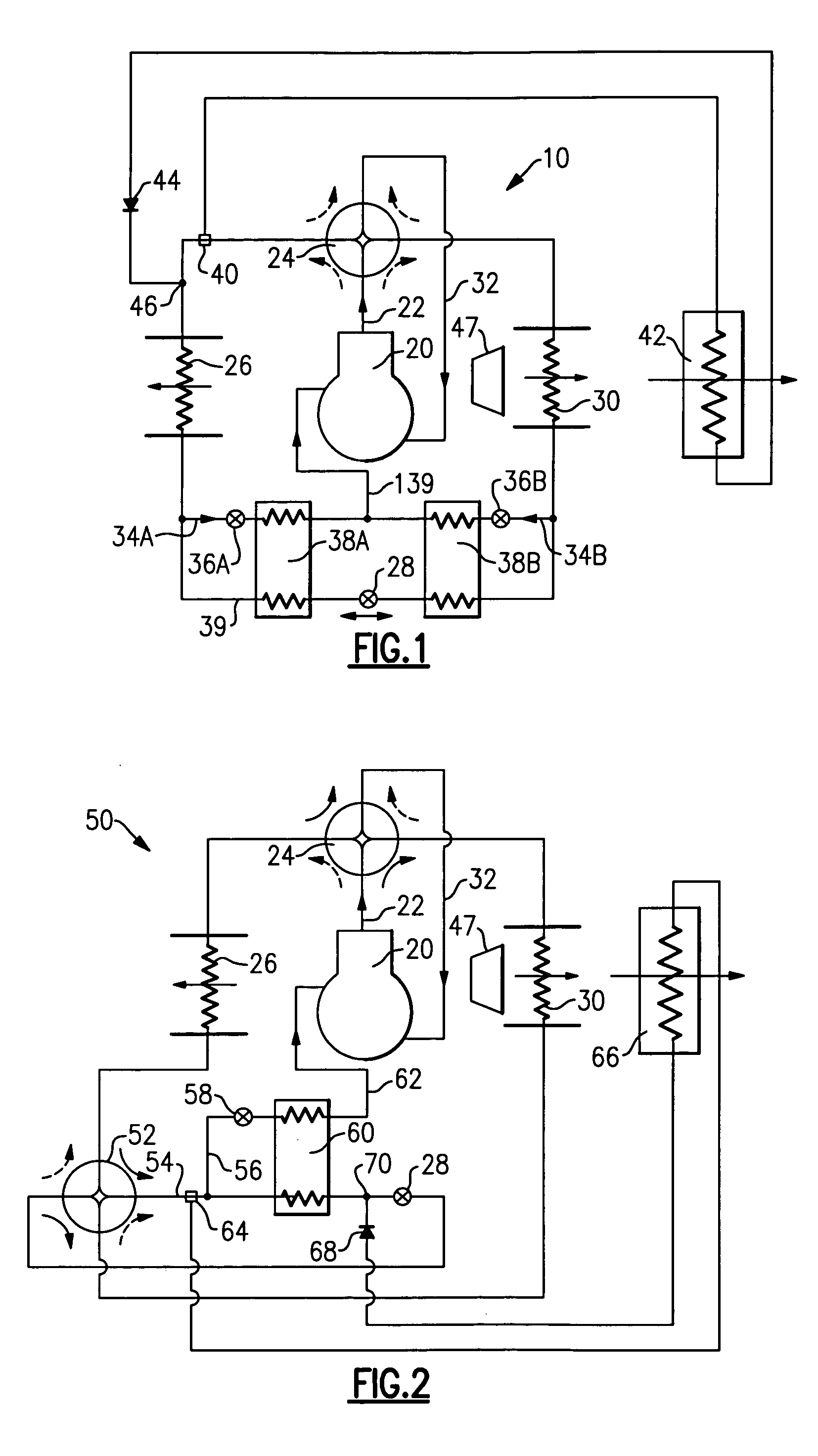
[0019]FIG. 1 shows a heat pump schematic 10 wherein a compressor 20 compresses a refrigerant and delivers that refrigerant to a discharge port 22. In a cooling mode, a four-way valve 24 routes the refrigerant to an outdoor heat exchanger 26, then to a main expansion device 28, and then to an indoor heat exchanger 30, from where it is returned through the four-way valve 24 and suction line 32 to the compressor 20. In a heating mode, a direction of the refrigerant flow through the system is essentially reversed, and the refrigerant flows from the compressor 20, through the four-way valve 24, through the indoor heat exchanger 30, main expansion device 28, to the outdoor heat exchanger 26, and then again through the four-way valve 24 and suction line 32 to the compressor 20. This general operation is as known in the art. As can be seen in the FIG. 1 drawing, the four-way valve 24 is controlled to either achieve cooling or heating mode of operation. As was mentioned earlier, if the expan...


PUM


Abstract

A heat pump system operates in heating and cooling modes. The heat pump is provided with both a reheat function and economizer circuit. The economizer circuit provides augmented performance to the heat pump, while the reheat coil allows enhanced control over temperature and humidity of the air supplied to the conditioned space. A bypass line around an outdoor heat exchanger is also provided to achieve additional flexibility of control for a sensible heat ratio. Selective operation of the abovementioned components and subsystems allows precise control over system operation parameters and hence satisfaction of a wide spectrum of sensible and latent load demands and improved reliability.

Description

BACKGROUND OF THE INVENTION [0001] This application relates to heat pump refrigerant systems that can be operated in either a cooling or heating mode, and wherein a reheat coil, and an economizer circuit are both incorporated into the system schematic and in combination provide augmented performance and enhanced control. [0002] Refrigerant systems are utilized to control the temperature and humidity of air in various indoor environments to be conditioned. In a typical refrigerant system operating in a cooling mode, a refrigerant is compressed in a compressor and delivered to a condenser (or outdoor heat exchanger in this case). In the condenser, heat is exchanged between outside ambient air and the refrigerant. From the condenser, the refrigerant passes to an expansion device, at which the refrigerant is expanded to a lower pressure and temperature, and then to an evaporator (or indoor heat exchanger). In the evaporator, heat is exchanged between the refrigerant and the indoor air, ...

Claims


Application Information

Patent Timeline
IPC IPC(8): F25B13/00F25B41/00
CPCF24F3/153F25B1/10F25B13/00F25B2313/0212F25B2313/02731F25B2600/2507F25B2313/02742F25B2400/04F25B2400/075F25B2400/13F25B2400/23F25B2313/02741
Inventor TARAS, MICHAEL F.LIFSON, ALEXANDER
Owner CARRIER CORP
Why Eureka
Try Eureka