Ball coupling device for keeping two sliding shafts articulated

a technology of sliding shaft and coupling device, which is applied in the direction of shafts, steering controls, bearings, etc., can solve the problems of increasing the fitting time, poor driving “feel”, and difficult fitting, so as to reduce the axial force, avoid axial jerks, and ensure good results

Active Publication Date: 2006-03-16
ROBERT BOSCH AUTOMOTIVE STEERING VENDOME SAS
View PDF4 Cites 35 Cited by
  • Summary
  • Abstract
  • Description
  • Claims
  • Application Information

AI Technical Summary

Benefits of technology

[0048] The device of the invention for coupling two shafts along their common axis therefore has the advantage of there always being two bearing areas for each of the interior and exterior shafts and for each row of balls, which are always in contact, even when no rotation torque is being transmitted.
[0049] Moreover, a reduced axial force is necessary when fitting on the production line. The precise fit of the coupling device of the invention avoids axial jerks when driving the vehicle, and guarantees good results in the endurance by avoiding play in the coupling. Moreover, the axial force is considerably reduced when rotation torque is being transmitted because of the rolling and sliding contact. Finally, the coupling device may easily be fitted within the existing space for automobile vehicle steering columns.

Problems solved by technology

To delay the onset of this play, the sliding fit of the two shafts at the fabrication stage is relatively tight, which calls for a relatively high axial force during assembly on the production line, which increases the fitting time and makes fitting more difficult.
The axial force during transmission of rotation torque is a function of the torque to be transmitted, and there is an increase in the sliding force linked to the torque to be transmitted and to the coefficient of friction, followed by a sudden axial unlocking, which causes jerks that compromise maintaining a good sliding fit with reduced play, leading to a poor driving “feel”.
This solution gives rise to problems absorbing axial movements under high torque; the sliding forces increase in proportion to the friction forces between the two parts.
Moreover, plays appear following wear of the injected plastics material.
This solution, which is satisfactory for sliding under torque, causes angular stiffness problems as it is directly proportional to the stiffness and to the prestressing of the springs.

Method used


Image

  • Ball coupling device for keeping two sliding shafts articulated
  • Ball coupling device for keeping two sliding shafts articulated
  • Ball coupling device for keeping two sliding shafts articulated

Examples


Embodiment Construction

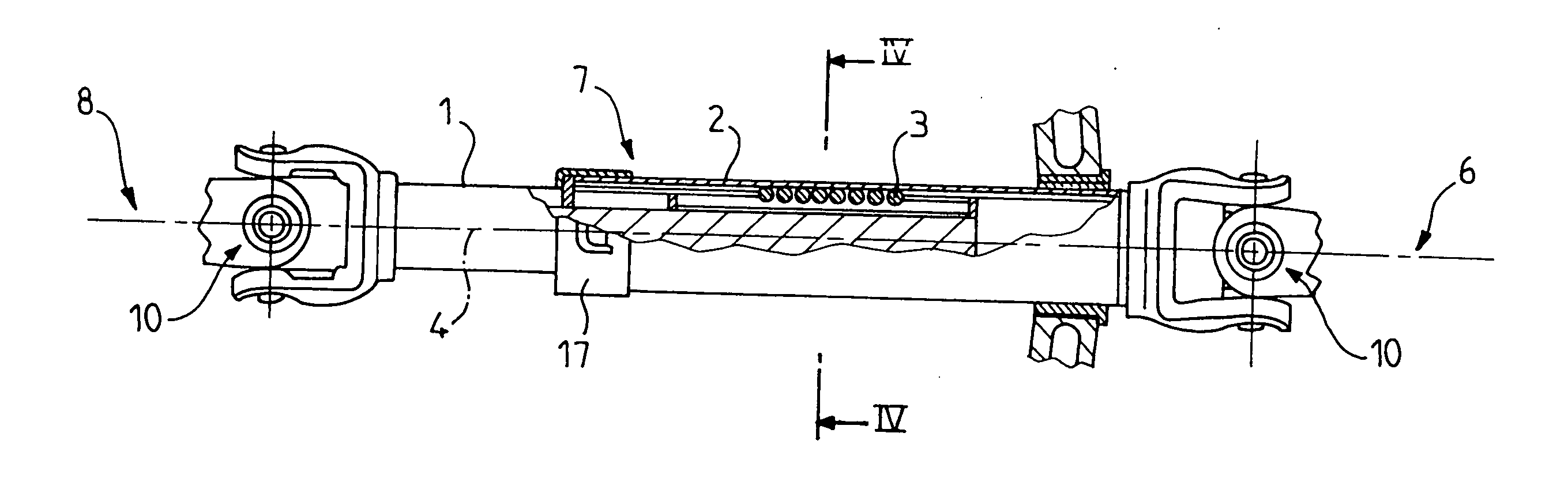
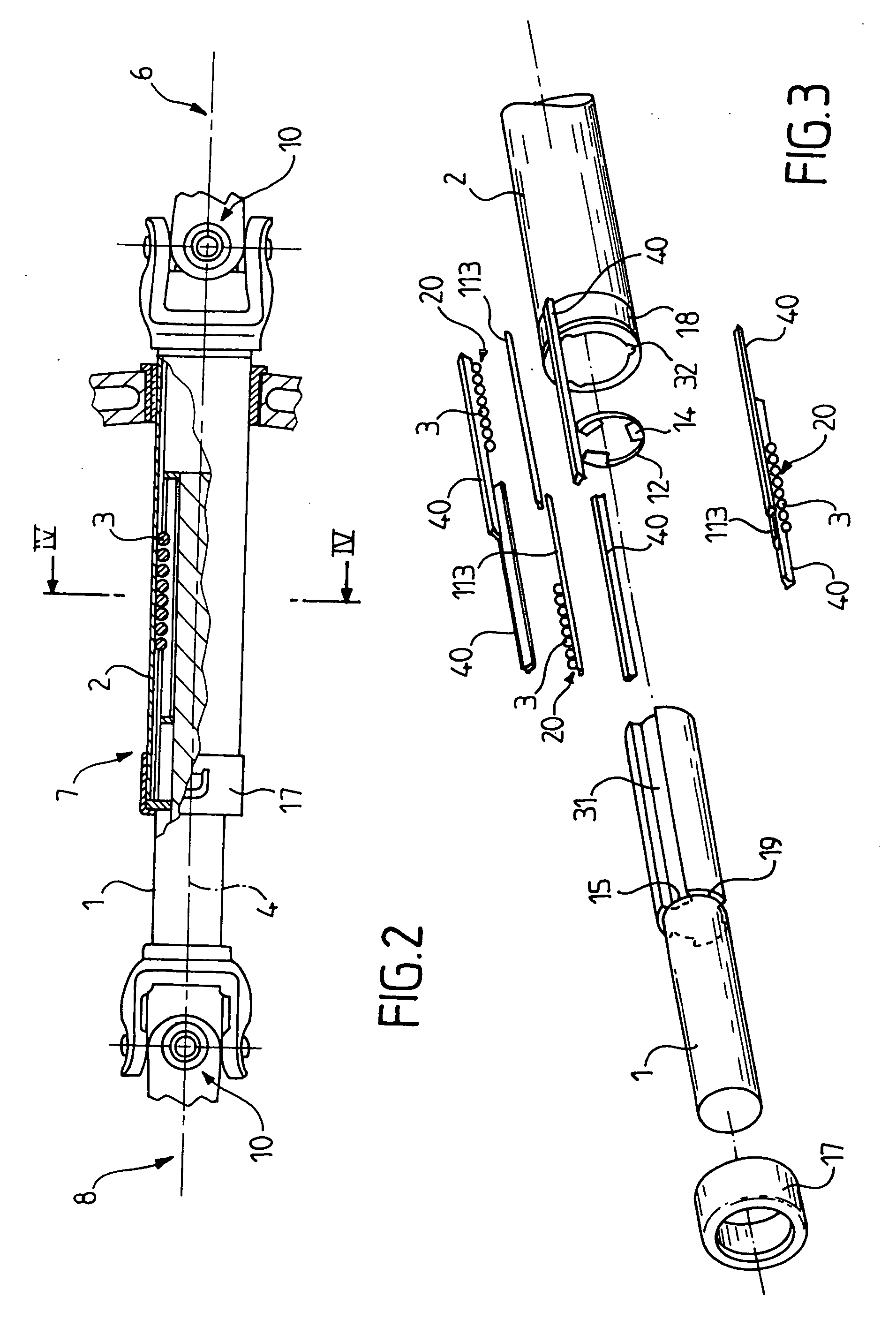
[0064] The invention relates to a device for rotationally coupling two shafts that slide one within the other along a common axis.

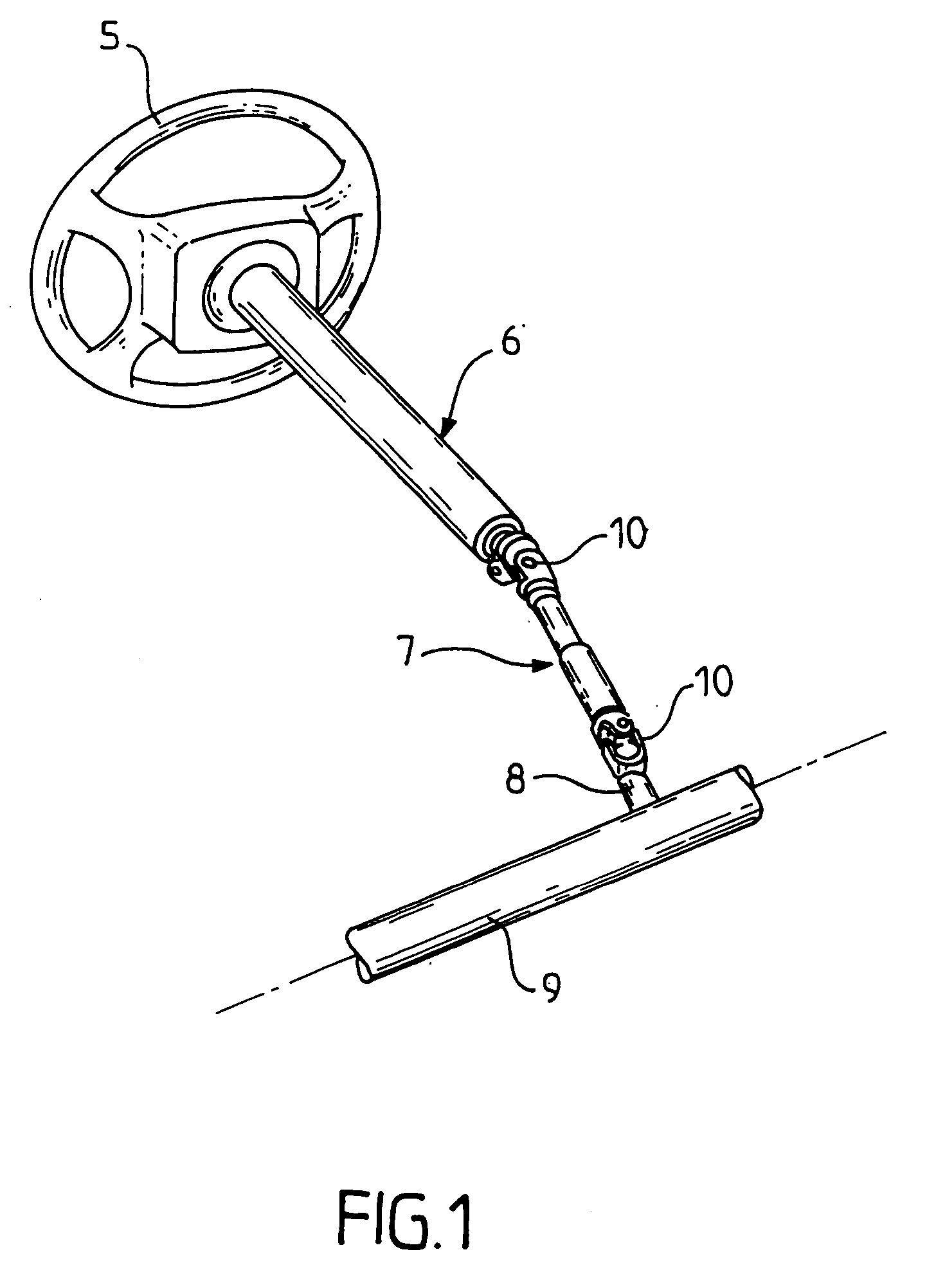
[0065] This coupling device applies particularly well to an automobile vehicle steering system, like the one shown diagrammatically in FIG. 1.

[0066] The steering system shown includes a steering column with a top column part 6 also called as a column top and an intermediate column part 7 also called as a intermediate shaft.

[0067] The top column part 6 is connected by its upper end to the steering wheel 5 and by its lower end to the intermediate column part 7.

[0068] The intermediate column part 7 is connected by its upper end to the top column part 6 and by its lower end to the steering box 8 of the steering rack 9.

[0069] The intermediate column part 7 is connected at each of its ends by means of a universal joint, designated 10 for both the top column part 6 and the steering box 8.

[0070] The remainder of the description relates to a coupling device ...


PUM


Abstract

Device for coupling an inner shaft and an outer shaft that slide in the direction of a common axis with balls disposed between the two shafts. The balls are disposed in axial grooves of the inner shaft and in axial grooves of the outer shaft. Each row of balls is held by a double spring member that bears on the groove and which pushes on two rolling tracks for the balls, which come into contact with the groove. The two rolling tracks are articulated at the junction of the groove and the inner shaft.

Description

BACKGROUND OF THE INVENTION [0001] 1—Field of the Invention [0002] The invention relates to a device for rotationally coupling two shafts sliding along their common axis. The coupling device of the invention applies in particular to an automobile vehicle steering column, in which it is fitted to the intermediate column part connected to the steering box or the upper column part connected to the steering wheel. [0003] 2—Description of the Prior Art [0004] In the more particular case of the intermediate shaft, the latter has a universal joint at each end: one universal joint is connected to the movement input of the steering box and the other universal joint is connected to the column top. For correct steering of modern automobile vehicles, it is necessary for the length of the intermediate shaft to be variable and to adapt to oscillations of the front drive train of the vehicle, which oscillations are caused by the profile and the surface state of the road covering. This characterist...

Claims


Application Information

Patent Timeline
Patent Type & Authority Applications(United States)
IPC IPC(8): B62D1/16F16C3/035F16C23/08F16C25/08F16C27/04F16C27/06F16C29/04F16C33/61F16D3/06
CPCF16C3/035F16C23/08F16C27/04F16D3/065F16C29/04F16C29/123F16C33/61F16C27/066F16C2326/24
Inventor BAHR, CHRISTOPHEARNAUD, JANVIER
Owner ROBERT BOSCH AUTOMOTIVE STEERING VENDOME SAS
Why Eureka
Try Eureka