
Multiple fluid heat pipe

Inactive Publication Date: 2006-03-16
SMITH MARK A +1
View PDF1 Cites 8 Cited by
  • Summary
  • Abstract
  • Description
  • Claims
  • Application Information

AI Technical Summary

Benefits of technology

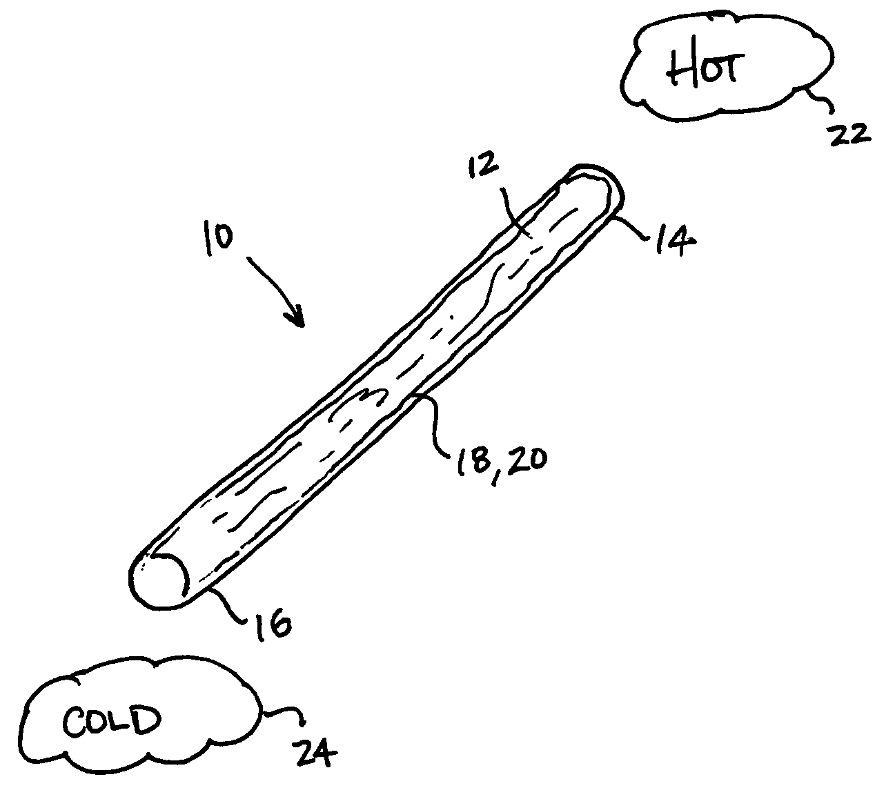
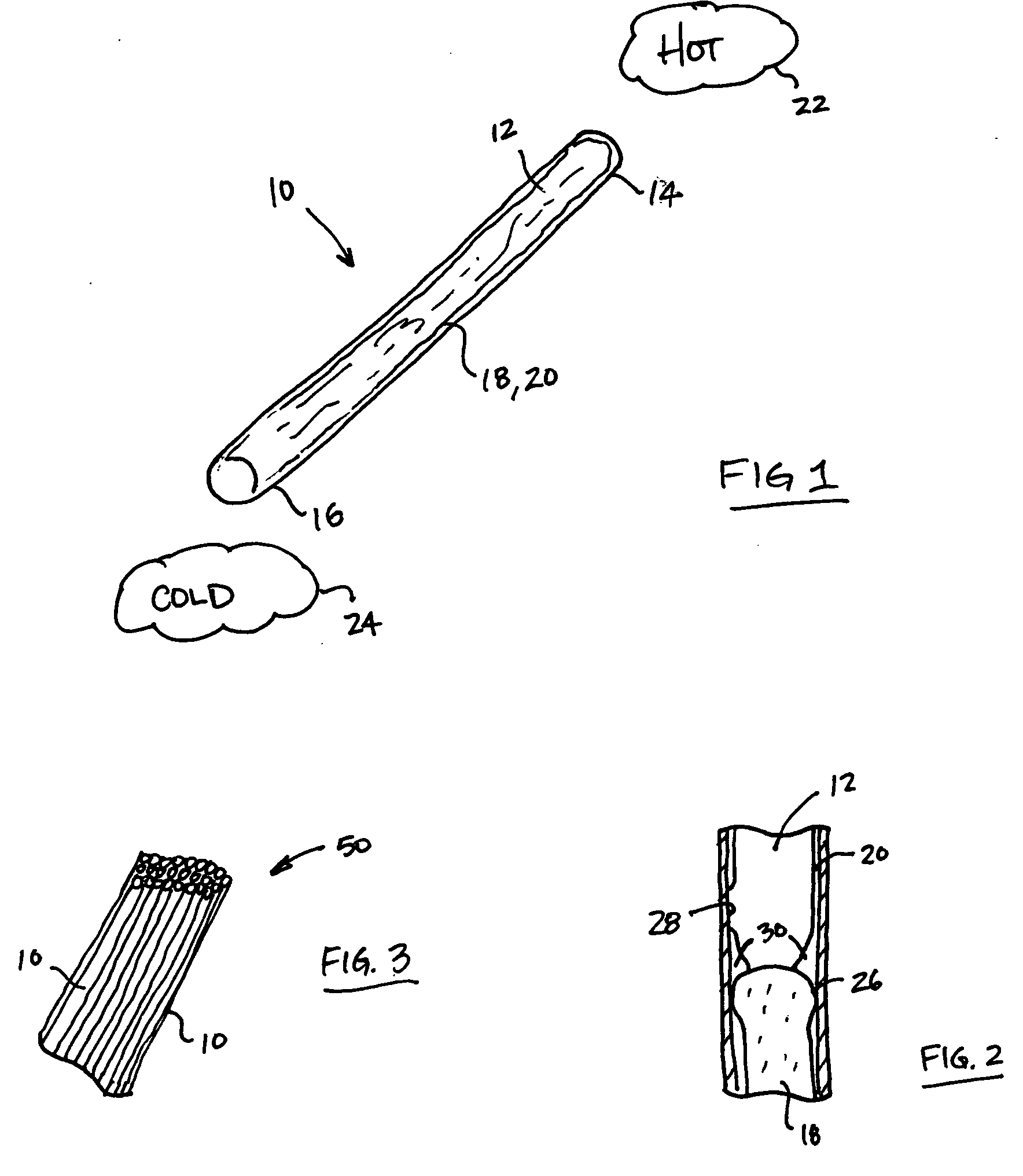
[0009] According to the principles of the present invention, a heat pipe having an advantageous construction and method of use is provided. The heat pipe having a fluid conduit, a first working fluid, having a first boiling point, disposed in the fluid conduit, and a second working fluid, having a second boiling point being different than the first boiling point, disposed in the fluid conduit. The first and second working fluids are disposed in the fluid conduit of the heat pipe such that during operating heat from the hot body causes the first working fluid to vaporize while the second working fluid remains in liquid phase. The vaporized first working fluid then carries the second working fluid through the fluid conduit to thermally transfer the heat.

Problems solved by technology

However, the usefulness of heat pipes is limited in cases where a hot object is positioned above a cold object.
In such case, the natural tendency for hot fluid to rise and cold fluid to sink tends to limit the operation of the heat pipe.
Thus, the operation of heat pipes is limited when used with hot objects positioned above cold objects.

Method used


Image

  • Multiple fluid heat pipe
  • Multiple fluid heat pipe

Examples


Embodiment Construction

[0015] The following description of the preferred embodiment is merely exemplary in nature and is in no way intended to limit the invention, its application, or uses.

[0016] According to the prior art, certain problems occur in the efficient transfer of a thermal load when a hot body to be cooled is located over or above the cold body. That is, in order to accomplish such cooling of the hot body, fluid would flow against its natural tendency (i.e. heat rises and cold sinks).

[0017] Typically, a heat pipe is a vacuum vessel containing a relatively small amount of working fluid. The vessel's inner surface is constructed or treated such that the working fluid covers the entire inner surface of the vessel as a thin layer. The vessel is initially evacuated and, thus, it only contains the liquid working fluid on the inner surface and the vapor phase of the fluid throughout the inner volume.

[0018] The amount of heat exchange a heat pipe can handle can be enormous. However, it is usually l...


PUM


Abstract

A heat pipe having a fluid conduit, a first working fluid, having a first boiling point, disposed in the fluid conduit, and a second working fluid, having a second boiling point being different than the first boiling point, disposed in the fluid conduit. The first and second working fluids are disposed in the fluid conduit of the heat pipe such that during operating heat from the hot body causes the first working fluid to vaporize while the second working fluid remains in liquid phase. The vaporized first working fluid then carries the second working fluid through the fluid conduit to thermally transfer the heat.

Description

CROSS-REFERENCE TO RELATED APPLICATIONS [0001] This application claims the benefit of U.S. Provisional Application No. 60 / 609,805, filed on Sep. 14, 2004. The disclosure of the above application is incorporated herein by reference.FIELD OF THE INVENTION [0002] The present invention relates to heat pipes and, more particularly, relates to a heat pipe employing multiple fluids for improved efficiency and operation. BACKGROUND OF THE INVENTION [0003] Heat pipe heat exchangers are well known in the field of heat recovery and dehumidification. Heat pipes rely on a phase change process to absorb heat by evaporation and release heat by condensation, transferring large amounts of heat energy with very little difference in temperature. [0004] Heat pipes typically comprise a condenser and an evaporator connected to each other in a closed system. The typical heat pipe comprises an enclosed tube system having one end forming an evaporator portion and having another, somewhat-cooler and lower-pr...

Claims


Application Information

Patent Timeline
IPC IPC(8): F28D15/00
CPCF28F23/00F28D15/02
Inventor SMITH, MARK A.MUSINSKI, DONALD
Owner SMITH MARK A
Learn More