
Radiation detector and detection method, and medical diagnostic apparatus employing same

a technology of radiation detector and detection method, applied in the direction of radiation intensity measurement, instruments, x/gamma/cosmic radiation measurement, etc., can solve the problems of high manufacturing cost, position-sensitive, and typical delicateness of collimators

Inactive Publication Date: 2006-03-16
SIEMENS HEALTHCARE GMBH
View PDF14 Cites 17 Cited by
  • Summary
  • Abstract
  • Description
  • Claims
  • Application Information

AI Technical Summary

Benefits of technology

[0009] In comparison a conventional detector arrangement with the collimator placed in front of the detectors, the inventive detector arrangement in that it also allows lateral radiation incidence and radiation incidence oriented at non-perpendicular angle onto the detector. In order to be able to localize the origin of this radiation, the radiation direction (thus the direction of incidence of the respective radiation quantum) is derived from the detected measurement values. The detector arrangement therefore also enables the spatial resolution required for the medical imaging without the use of collimators. The decisive advantage is thereby achieved of no collimators being necessary and a significantly higher fraction of the available radiation is evaluated and used for the imaging. In particular in the nuclear imaging modalities (SPECT, PET), in which the radiation is distributed over the entire examination volume and is not specific due to the nuclear decay, the invention achieves a significant increase in efficiency, i.e. the available radiation is used more efficiently for image generation. In the reverse, this means that the dose to be administered to the patient can be smaller. The exposure of the patient is thereby reduced.
[0010] Additionally, a significant technical simplification in the technical complexity of the apparatus and therewith a significant cost savings are achieved via the omission of the collimators. The collimators are typically extremely delicate, position-sensitive and therewith very elaborate to manufacture.
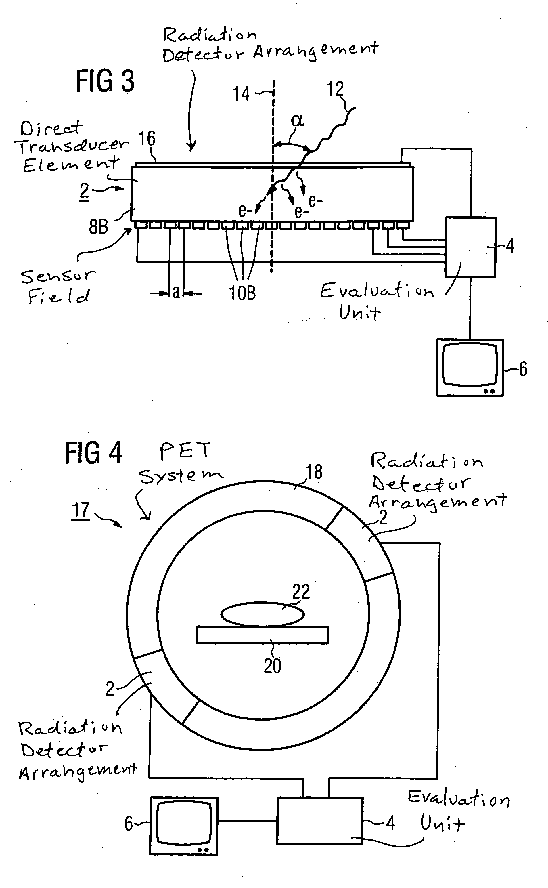
[0018] Such a detector arrangement is preferably used in a medical diagnostic system for a nuclear medical diagnostic modality such as PET or SPECT. As an alternative to use in a nuclear medical diagnostic modality, the detector arrangement can be used in an x-ray medical diagnostic method, in particular in a computed tomography system. The use of the detector arrangement leads to a higher efficiency of the radiation evaluation, as well as to an apparatus simplification due to the omission of a collimator, and additionally to a lower exposure of the patient, in particular in the nuclear medical diagnostic modality (which is of decisive importance in the medical field).
[0022] Given use for computed tomography, radiation portions that (relative to the surface normals) strike at an angle on the detector are preferably identified as scatter radiation and are not further used for imaging. Interfering scatter radiation portions therefore can be eliminated in this manner without the use of a collimator.

Problems solved by technology

The collimators are typically extremely delicate, position-sensitive and therewith very elaborate to manufacture.

Method used


Image

  • Radiation detector and detection method, and medical diagnostic apparatus employing same
  • Radiation detector and detection method, and medical diagnostic apparatus employing same
  • Radiation detector and detection method, and medical diagnostic apparatus employing same

Examples


Embodiment Construction

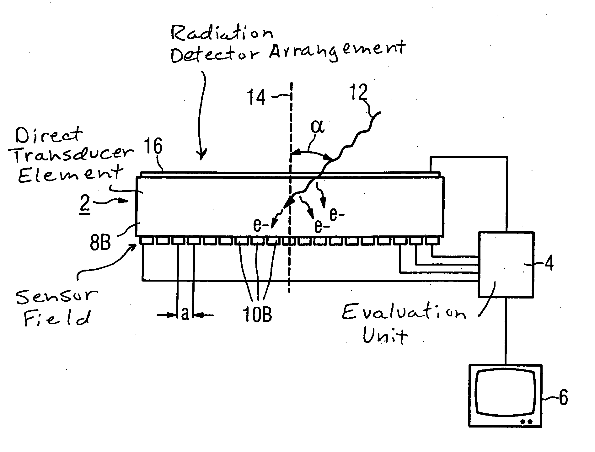
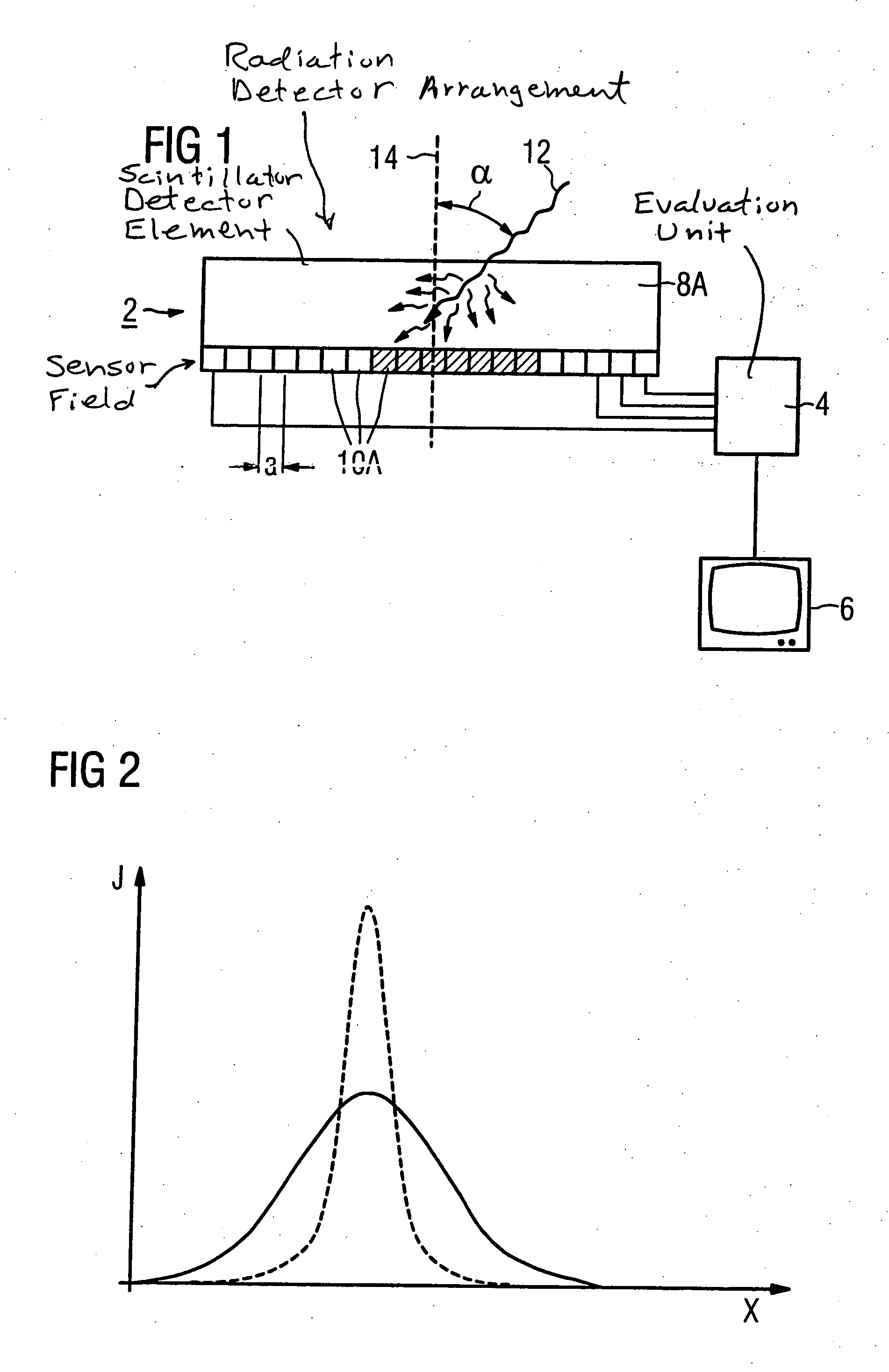
[0027] As shown in FIGS. 1 and 3, a detector arrangement HAS a detector 2, an evaluation unit 4 as well as a display element 6 connected with the evaluation unit 4. The detector 2 in FIG. 1 has a detector element 8A as well as a sensor field, arranged on the underside of the detector element 8A, with a number of sensor elements 10A arranged in a matrix. The detector 2 in FIG. 3 has a detector element 8B and sensor elements 10B. In each embodiment, the average separation a of two adjacent sensor elements 10A, 10B (thus the average separation a between their center points) is in the range between 10 μm-500 μm. Each of the sensor elements 10A, 10B in the matrix is connected with the evaluation unit 4. For better clarity, in the FIGS. 1 and 3 only some of the sensor elements 10A, 10B are shown connected with the evaluation unit 4.

[0028] In the exemplary embodiment of FIG. 1, the detector element 8A is a scintillator and the sensor elements 10A are photosensor elements. The sensor field...


PUM


Abstract

In a detector arrangement for a medical diagnosis apparatus as well as a medical imaging diagnostic method, radiation quanta striking a detector are detected and evaluated with spatial resolution. The use of collimators is thereby omitted, such that radiation quanta that strike at a non-perpendicular angle to the detector are also evaluated. For spatial resolution of the origin of the radiation quantum, the spatial distribution of sensor elements of the detector that emit a signal upon incidence of a radiation quantum is evaluated. A higher efficiency of the radiation evaluation is enabled and, particularly in nuclear medical diagnostic methods, the radiation exposure of the patient can be distinctly reduced.

Description

BACKGROUND OF THE INVENTION [0001] 1. Field of the Invention [0002] The present invention concerns a radiation detector arrangement for a medical diagnostic apparatus, a medical diagnostic system with such a detector arrangement, as well as a medical imaging diagnostic method. [0003] 2. Description of the Prior Art [0004] Various imaging diagnostic methods are known in the field of medicine, such as, for example, computed tomography (CT), in which the patient to be examined is irradiated with x-rays from a number of different directions and the x-rays are detected by a detector as projection datasets, which are combined for generation of an image. [0005] In addition to this method based on x-ray radiation, what are known as nuclear medicine methods also are known such as, for example, PET diagnostics (positron emission tomography) and SPECT diagnostics (single photon emission computed tomography). In each of these modalities, the patient is injected with a radioactive substance and ...

Claims


Application Information

Patent Timeline
Patent Type & Authority Applications(United States)
IPC IPC(8): G01T1/24
CPCG01T1/2928G01T1/2018G01T1/2006
Inventor FRITZLER, SVENHEISMANN, BJORN
Owner SIEMENS HEALTHCARE GMBH
Learn More