
Compressor bypass valve for use in multistage supercharging

a compressor bypass and supercharging technology, which is applied in the direction of valve operating means/release devices, functional valve types, machines/engines, etc., can solve the problems of relatively slow valve opening, rapid and high build-up of boost pressure, etc., and achieve the effect of reducing the flow of fresh air through the high-pressure compressor

Active Publication Date: 2006-03-16
ROBERT BOSCH GMBH
View PDF32 Cites 25 Cited by
  • Summary
  • Abstract
  • Description
  • Claims
  • Application Information

AI Technical Summary

Benefits of technology

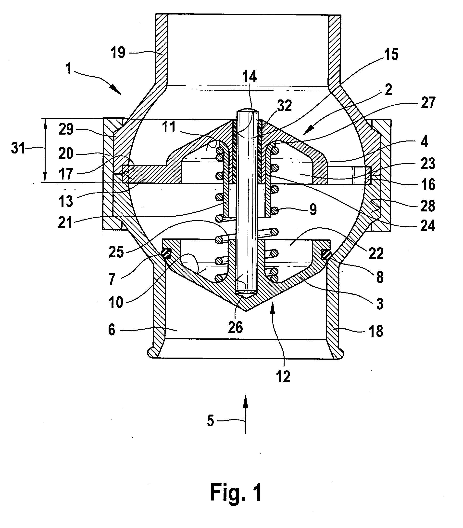
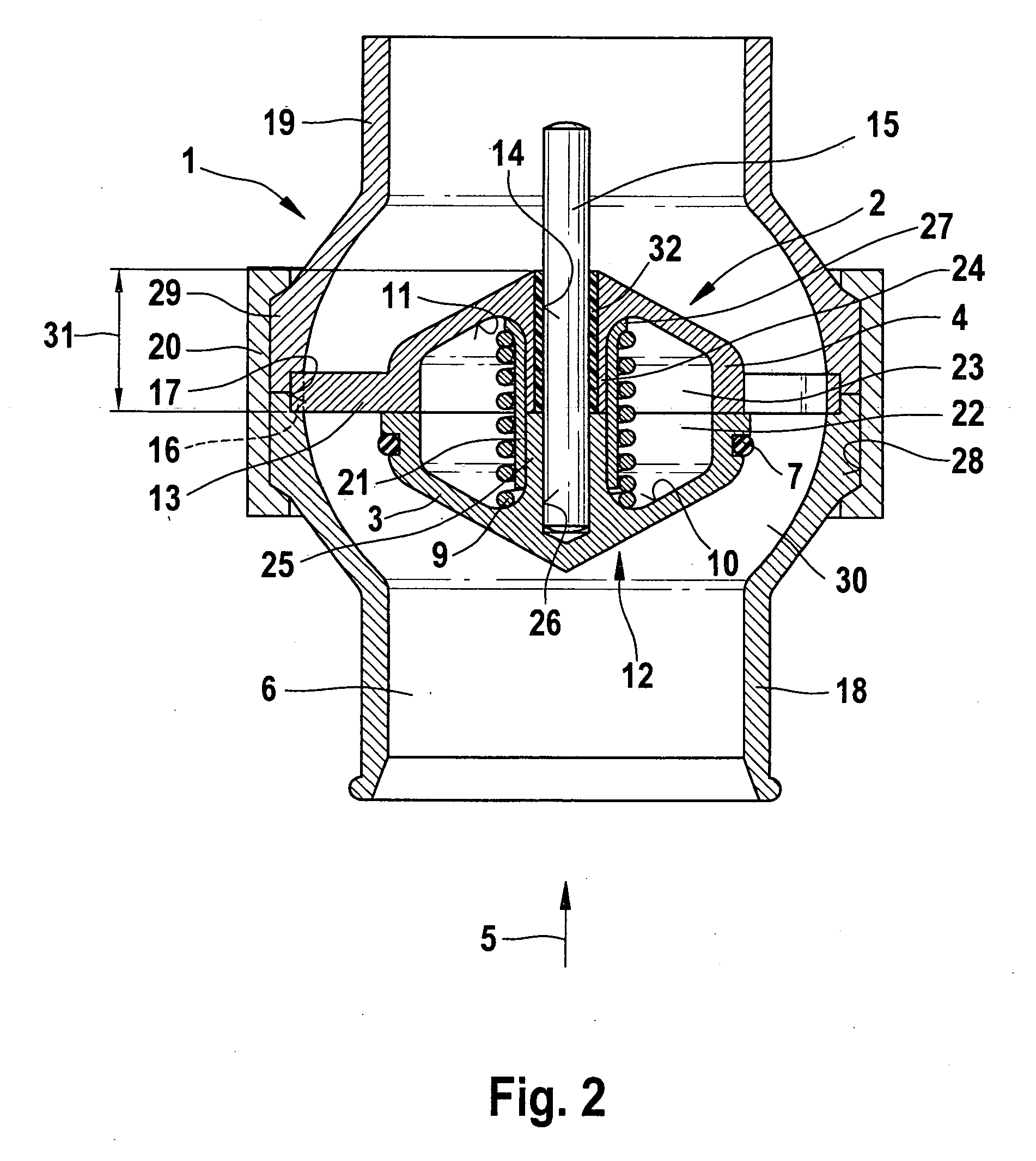
[0005] The inventive compressor bypass for multistage supercharging in internal combustion engines equipped with a supercharging system, e.g. an exhaust gas turbocharger, comprises a displacement body accommodated in a valve housing. The displacement body is divided into at least two displacement parts, of which a first displacement part, facing the upstream side, closes or opens the compressor bypass. The advantage of the inventive compressor bypass comprising a displacement body accommodated in a valve housing over the compressor sequencing valve comprising a displacement body known from the prior art, as used in sequential supercharging, is that owing to the two-part displacement body, only a very small mass must be moved in order to close or open the bypass. Rapid opening and closing can be ensured in this manner. Due to this rapid opening, when the choke limit is reached, a portion of the fresh air is immediately routed through the compressor bypass and the flow of fresh air through the high-pressure compressor is thereby reduced. This prevents the high-pressure compressor from acting as a throttle and the pressure from dropping as the flow passes through the high-pressure compressor.
[0007] Imparting a flow-promoting or streamlined shape to the displacement body reduces pressure losses as the flow passes around the displacement body. This prevents any pressure drop as the flow passes through the bypass.

Problems solved by technology

This produces a very rapid and high build-up of boost pressure.
This makes for relatively slow opening of the valve.

Method used


Image

  • Compressor bypass valve for use in multistage supercharging
  • Compressor bypass valve for use in multistage supercharging
  • Compressor bypass valve for use in multistage supercharging

Examples


Embodiment Construction

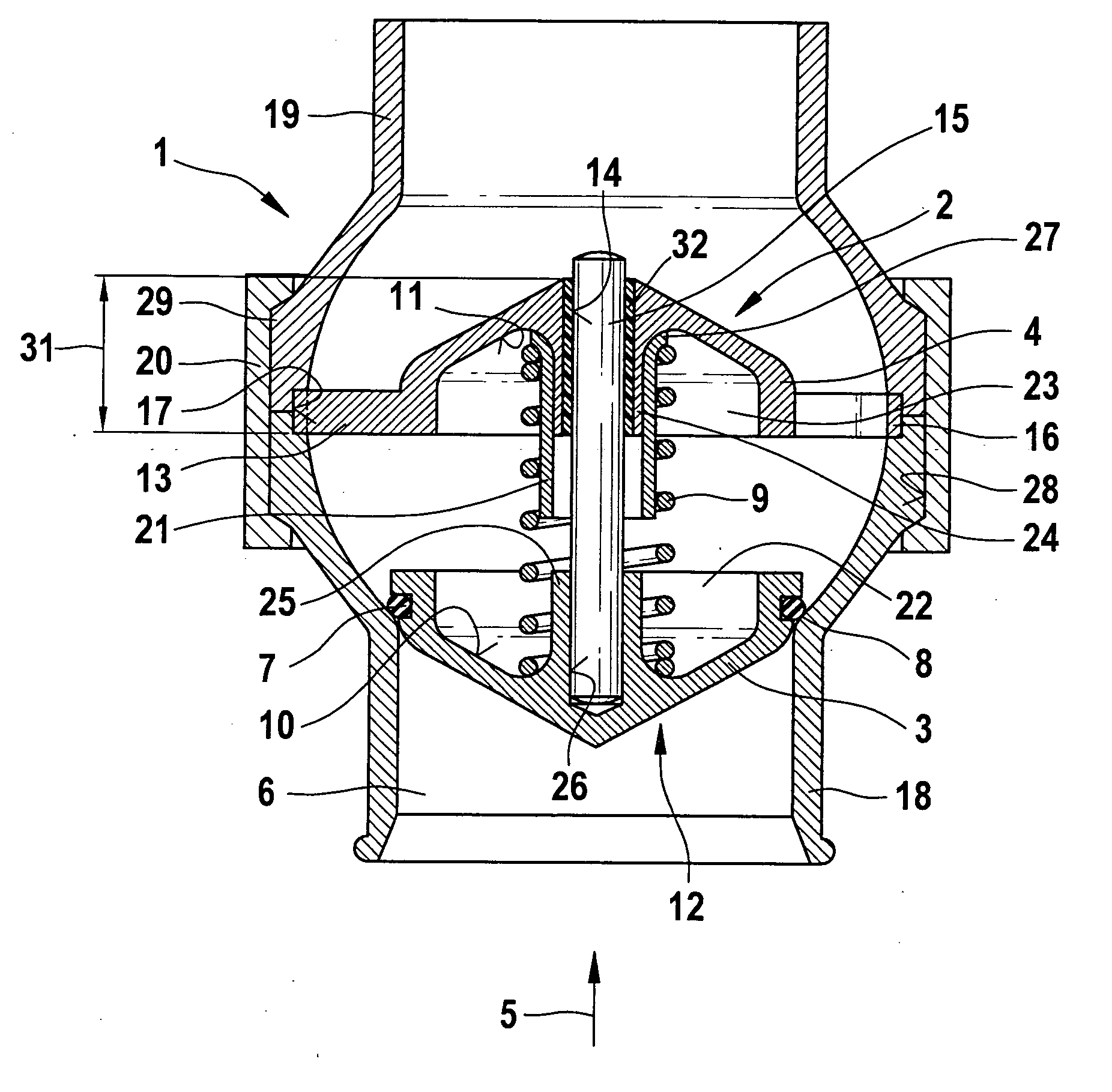
[0019]FIG. 1 shows a compressor bypass valve with a displacement body accommodated therein and the throat closed.

[0020] In a multistage, preferably two-stage, supercharging system comprising an exhaust gas turbocharger in an internal combustion engine, the fresh air is first compressed in a low-pressure compressor. The fresh air so compressed is preferably cooled in an intercooler before being delivered to a high-pressure compressor stage. When very small volumes of air are present, the fresh air is compressed in the high-pressure compressor stage. As the demand for fresh air increases, the choke limit of the high-pressure compressor is reached. To keep the high-pressure compressor from functioning as a choke, when the fresh air mass flow rate is above the choke limit of the high-pressure compressor, a portion of the fresh air is diverted around the high-pressure compressor through a compressor bypass 6.

[0021] Compressor bypass 6 comprises a valve housing 1 with a displacement bod...


PUM


Abstract

A compressor bypass valve for multistage supercharging an internal combustion engine equipped with a supercharging system. The valve includes a displacement body accommodated in a valve housing. The displacement body is divided into a first displacement part and a second displacement part. The first displacement part, facing the upstream side, moves to close or open the bypass in response to a pressure differential.

Description

BACKGROUND OF THE INVENTION [0001] To increase the power of internal combustion engines, exhaust gas turbochargers are used. Due to the large operating range of internal combustion engines in passenger vehicles, the exhaust gas turbocharger must be regulated in order to achieve a set boost pressure. To this end, in multistage supercharging the fresh air is compressed first in a low-pressure compressor and then in a high-pressure compressor. When large volumes of fresh air are present, the choke limit of the high-pressure compressor is exceeded. To keep the high-pressure compressor from functioning as a choke in this case, some of the fresh air can be diverted around the high-pressure compressor through a compressor bypass. When the volume of fresh air is below the choke limit of the high-pressure compressor, the compressor bypass is closed. [0002] To keep the pressure build-up in the exhaust gas turbocharger from not [sic] lagging when the temperature of the exhaust gas is low and t...

Claims


Application Information

Patent Timeline
Patent Type & Authority Applications(United States)
IPC IPC(8): F16K31/44
CPCF02B37/013Y02T10/144F16K15/063F02B37/16Y10T137/7923Y10T137/7852Y10T137/3421Y10T137/7856Y02T10/12
Inventor VOGT, GUENTHER
Owner ROBERT BOSCH GMBH
Learn More