Voice coil motor apparatus for positioning

a voice coil motor and positioning technology, applied in the direction of electronic commutators, instruments, printers, etc., can solve the problems of cost and space, current efforts to reduce components, and the internal space of most compact electronic devices is not enough to meet such requirements

Inactive Publication Date: 2006-03-16
VASSTEK INT
View PDF5 Cites 29 Cited by
  • Summary
  • Abstract
  • Description
  • Claims
  • Application Information

AI Technical Summary

Benefits of technology

[0009] The primary objective of the present invention is to provide a voice coil motor apparatus for positioning that can achieve precision positioning within a prescribed range.

Problems solved by technology

Most compact electronic devices simply do not have enough internal space to accommodate such requirements, and it is also against current efforts of downsizing components.
Conventional voice coil motors have the following disadvantages when applied to the positioning of the lens for the auto-focus module of a miniature camera: (1) Conventional voice coil motors often employ non-contact position sensors such as linear scale, fiber-optic displacement detector, or laser displacement detector to feed back the displacement information of the movable part.
However, for the application of a miniature camera, the sever limitation on the cost and the space will make the usage of the aforementioned position sensors almost impossible.
(2) The flexible U-shaped power cable adopted in the voice coil motor needs sufficiently large space to maintain its life cycle under continuous twisting, which in turn will be against efforts to downsize components in a miniature camera.
This therefore results in considerable power consumption, which is a negative effect for the application of the voice coil motor in a battery-powered camera.
Therefore, developing a low-cost and small position feedback sensor and minimizing the negative effects due to the flexible power cable are some of the issues to be dealt with, if a voice coil motor is to be used in the positioning of the movable lens of miniature cameras.

Method used


Image

  • Voice coil motor apparatus for positioning
  • Voice coil motor apparatus for positioning
  • Voice coil motor apparatus for positioning

Examples


Embodiment Construction

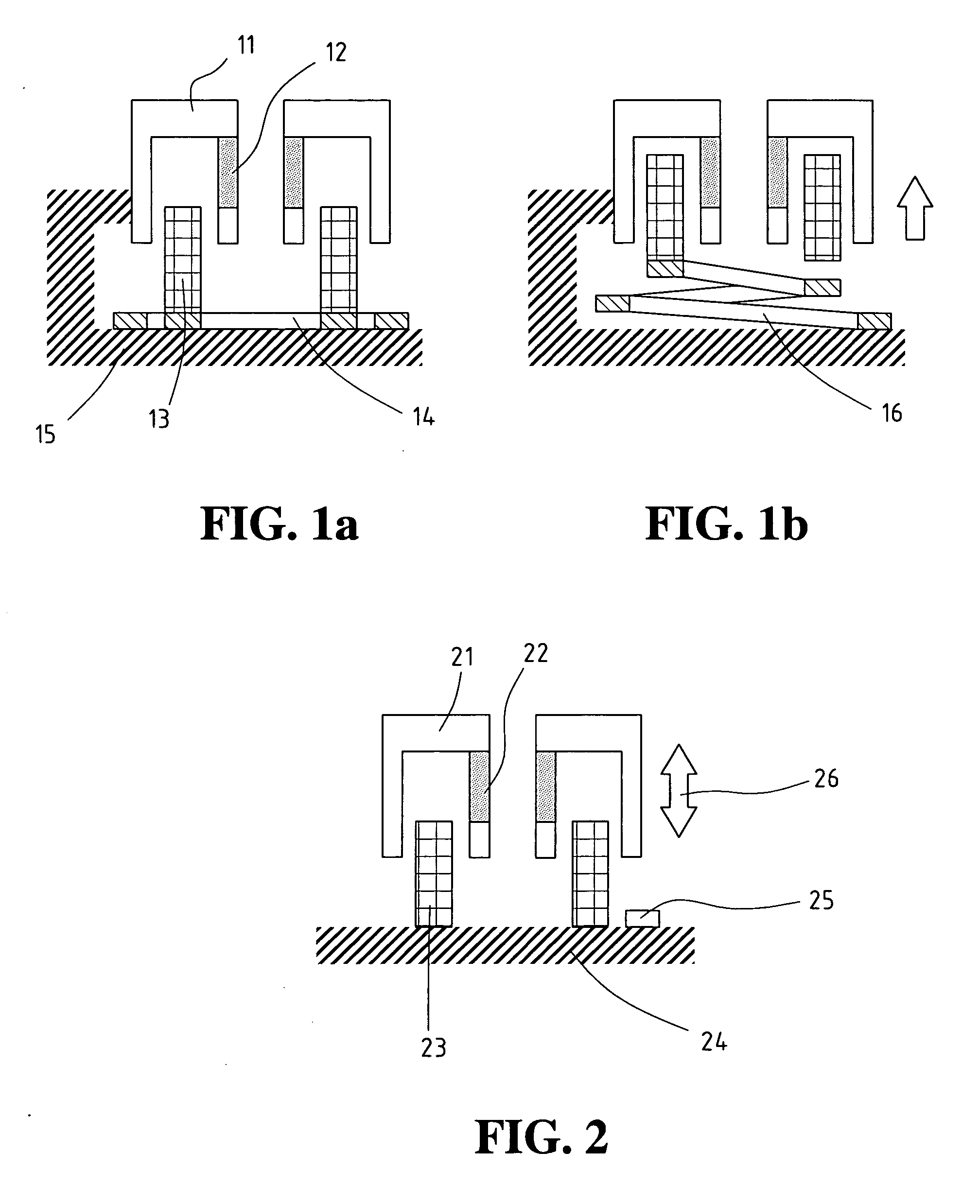
[0032] Referring to FIGS. 1A and 1B, the presently described voice coil motor includes a movable part and a stationary part. Preferably, the electrical circuit of the voice coil motor is movable, being composed of a coil winding 13 and a flexible circuit board as the power cable 14, and the magnetic circuit is stationary, being composed of an iron yoke 11 and a permanent magnet 12, fixed on a substrate 15. When the motor is first started, the coil winding 13 remains at one end, and the flexible power cable is coiled as a flat pack, but when the coil winding 13 is supplied with exciting current, the coil winding 13 moves to another end as shown in FIG. 1B. Since one end of the power cable 14 is connected to the coil winding 13, when the coil winding 13 moves to another end, the coiled power cable is stretched out in a spring-up posture 16 as shown in FIG. 1B.

[0033] When the above-mentioned voice coil motor with short stroke is used in auto-focus lens control module of a miniature ca...


PUM

PropertyMeasurementUnit
motion forceaaaaaaaaaa
relative displacementaaaaaaaaaa
magnetic fieldaaaaaaaaaa

Abstract

A voice coil motor apparatus for positioning is disclosed. The voice coil motor is used by the auto-focus lens control module of a miniature camera. The apparatus contains a voice coil motor, a position feedback sensor, and a positioning controller. The voice coil of the voice coil motor can be either movable or stationary, where in the former case the attached power cable is a flexible circuit board, and in the latter case the power cable is fixed. The position feedback sensor includes a photo interrupter, a light reflector, and a bias circuit used for tracking any displacement of the movable part of the motor. The positioning controller uses the voltage signals to be processed through a proportional-integral-differential computation unit to manipulate an output current for accurate positioning of the movable part of the motor within a prescribed range.

Description

BACKGROUND OF THE INVENTION [0001] 1. Field of the Invention [0002] The present invention relates to a voice coil motor (VCM) apparatus for positioning, and in particular to an apparatus for positioning the movable lens of an auto-focus module used in a miniature camera. [0003] 2. The Related Art [0004] A conventional voice coil motor includes a movable part and a stationary part as shown in FIG. 9. The stationary part, fixed on the substrate 92, is composed of a permanent magnet 911 and an iron yoke 912 to produce a magnetic field through the air gap 913 of the magnetic circuit. The movable part is composed of a coil winding 931 and a power cable 932 with one end being connected to the coil winding 931. When a current is supplied to the coil winding 931, the coil winding will move through the air gap as a result of the interaction between the current and the magnetic field. [0005] As the coil winding 931 is the movable part of the voice coil motor, a flexible power cable 932, with ...

Claims


Application Information

Patent Timeline
Patent Type & Authority Applications(United States)
IPC IPC(8): H02K41/00H02K35/00G11B21/24G02B7/28G03B5/00G03B13/36H02K33/16H02K33/18
CPCH02K41/0358H02P6/16H02P7/025H02P25/034
Inventor TSENG, YU-KUANG
Owner VASSTEK INT
Why Eureka
Try Eureka