Piezoelectric element, liquid droplet ejection head, and liquid droplet ejection apparatus

a technology of liquid droplet ejection and piezoelectric element, which is applied in the direction of piezoelectric/electrostrictive transducer, inking apparatus, respirator, etc., can solve the problems of inability to eject ink liquid droplets, the degradation of piezoelectric characteristic of piezoelectric element itself, etc., to prevent the degradation improve the effect of piezoelectric body layer repair and excellent

Inactive Publication Date: 2006-03-16
FUJIFILM BUSINESS INNOVATION CORP
View PDF14 Cites 30 Cited by
  • Summary
  • Abstract
  • Description
  • Claims
  • Application Information

AI Technical Summary

Benefits of technology

[0024] As described above, according to the present invention, the first metal oxide layer is disposed adjacent to the piezoelectric body layer on the lower potential side when an electric field in a predetermined direction is applied to the piezoelectric body layer, and which suppresses the degradation of the piezoelectric body layer that is caused by application of the electric field; and the second metal oxide layer is disposed adjacent to the piezoelectric body layer on the higher potential side of the electric field which is applied to the piezoelectric body layer, and which, by applying an electric field in the direction reverse to the electric field, repairs the piezoelectric body layer degraded. Thus, the present invention has excellent effects in that it can provide a piezoelectric element, a liquid droplet ejection head, and a liquid droplet ejection apparatus which are capable of repairing the degradation of the piezoelectric characteristic.

Problems solved by technology

However, although, with the art as disclosed in Laid-Open Publication 2003-80698, the variation in the amount of ink liquid droplet ejected can be suppressed, there has been a problem that the longer the period of time of driving the liquid droplet ejection head, the heavier the degradation of the piezoelectric characteristic of the piezoelectric element itself will be.
If the degradation of the piezoelectric element is progressed, the amount of displacement when the electric field is applied is reduced, which may make the ejection of ink liquid droplets impossible.

Method used


Image

  • Piezoelectric element, liquid droplet ejection head, and liquid droplet ejection apparatus
  • Piezoelectric element, liquid droplet ejection head, and liquid droplet ejection apparatus
  • Piezoelectric element, liquid droplet ejection head, and liquid droplet ejection apparatus

Examples


Embodiment Construction

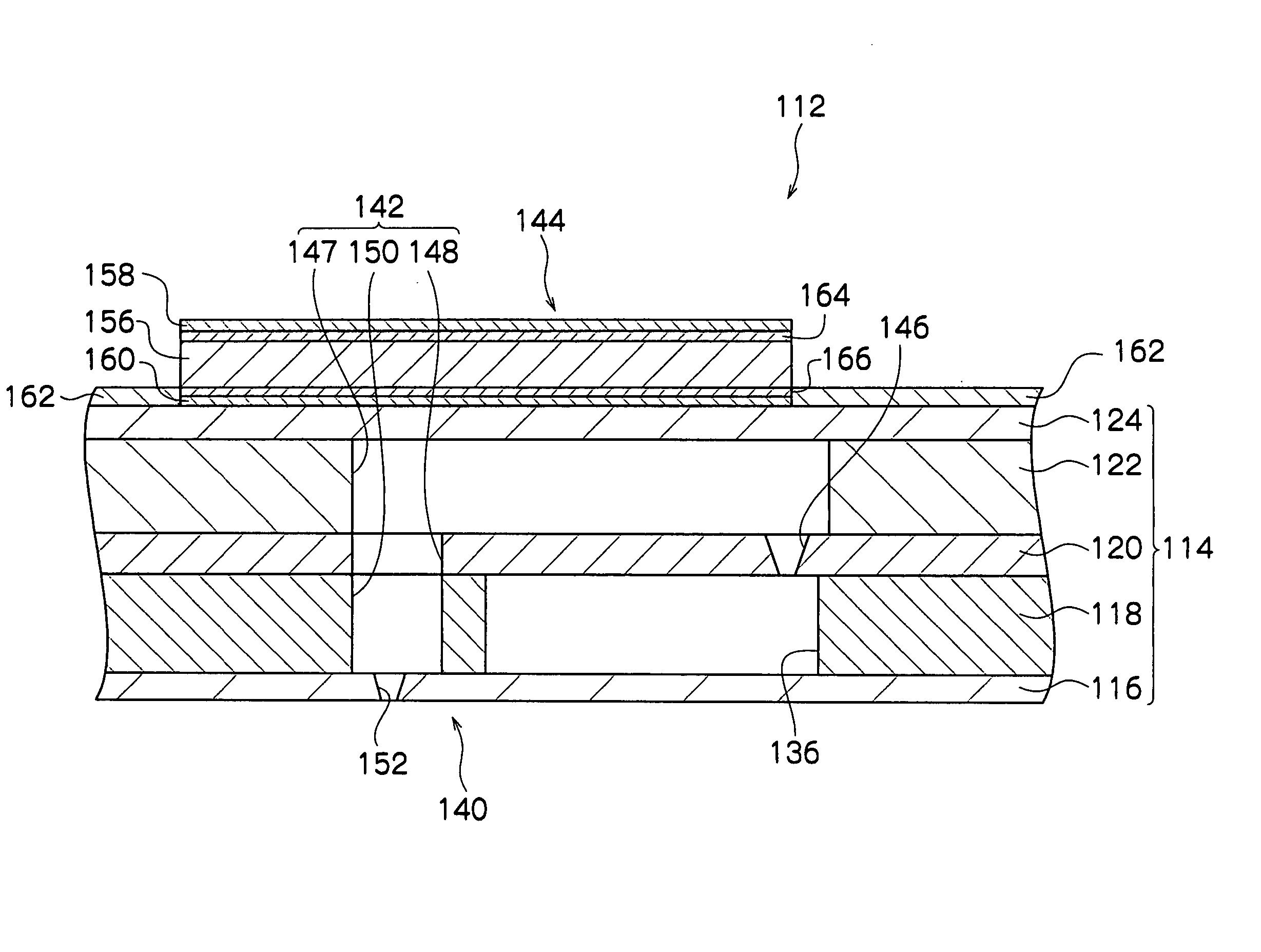
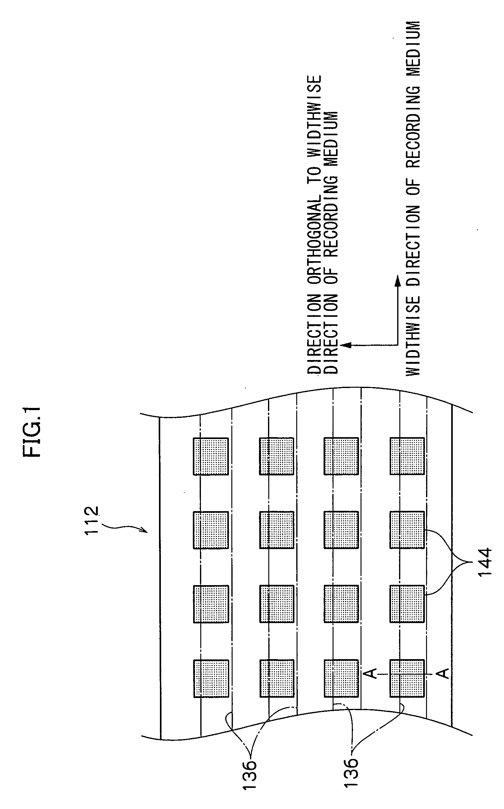
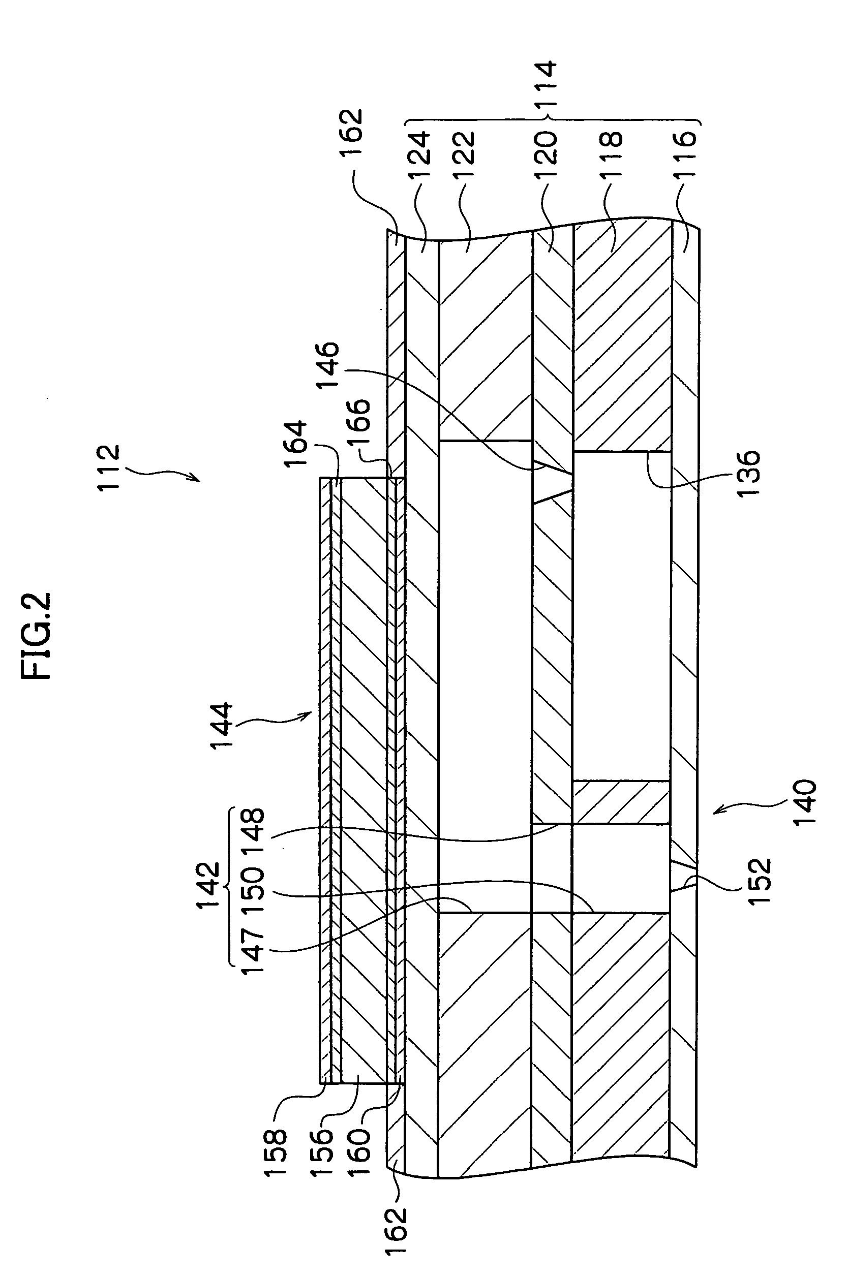
[0034] Hereinafter, the present embodiment will be explained in detail with reference to the drawings.

[0035] First, a piezoelectric body layer constituting a piezoelectric element according to the present embodiment will be described. As a material constituting the piezoelectric body layer, the material is not specifically limited; however, it is preferably a well-known piezoelectric body material which can be deformed when subjected to a voltage. However, as a piezoelectric element for liquid droplet ejection, for example, it is preferable from the viewpoint of the necessary characteristic that a lead zirconate titanate (PZT) family piezoelectric body, which has a relatively high piezoelectric constant, be used. Especially, modified PZT, which is formed by adding a donor (Nb, for example) to PZT, has a high piezoelectric constant, and is suited for liquid droplet ejection applications.

[0036] The thickness of the piezoelectric body layer is not specifically limited; however, it is...


PUM

PropertyMeasurementUnit
thicknessaaaaaaaaaa
thicknessaaaaaaaaaa
thicknessaaaaaaaaaa

Abstract

A metal oxide layer is disposed on the lower potential side when an electric field in a predetermined direction is applied to the piezoelectric body which is deformed by an applied electric field, and compensates for the oxygen vacancies which are generated in the piezoelectric body by applying the electric field. A second metal oxide layer is disposed on the higher potential side of the electric field applied to the piezoelectric body, and by applying an electric field in the direction reverse to the electric field, compensates for the oxygen vacancies which are accumulated in the piezoelectric body, thus degradation of the piezoelectric characteristic of a piezoelectric element can be repaired.

Description

CROSS-REFERENCE TO RELATED APPLICATION [0001] This application claims priority under 35 USC 119 from Japanese Patent Application No. 2004-267349, the disclosure of which is incorporated by reference herein. BACKGROUND OF THE INVENTION [0002] 1. Field of the Invention [0003] The present invention relates to a piezoelectric element including a piezoelectric body layer which is deformed in accordance with a voltage applied thereto, a liquid droplet ejection head including plural the piezoelectric elements, and a liquid droplet ejection apparatus including the liquid droplet ejection head. [0004] 2. Description of the Related Art [0005] Conventionally, liquid droplet ejection apparatuses, such as ink jet printers, comprise a liquid droplet ejection head for ejecting ink liquid droplets. This liquid droplet ejection head comprises plural liquid droplet ejection ports, plural pressure generating chambers each connected to the respective liquid droplet ejection ports, and a piezoelectric e...

Claims


Application Information

Patent Timeline
Patent Type & Authority Applications(United States)
IPC IPC(8): B41J29/38B41J2/015B41J2/045B41J2/055B41J2/135B41J2/14B41J2/145H01L41/09H01L41/187H01L41/22H01L41/29
CPCB41J2/14233Y10T29/42B41J2202/03
Inventor YAGI, TAKASHI
Owner FUJIFILM BUSINESS INNOVATION CORP
Why Eureka
Try Eureka