Illumination optical system, exposure apparatus, and exposure method

an optical system and optical system technology, applied in the direction of microlithography exposure apparatus, printers, instruments, etc., can solve the problems of not always secure the appropriate illumination conditions that are required to precisely transfer the mask pattern onto the wafer

Inactive Publication Date: 2006-03-16
NIKON CORP
View PDF15 Cites 310 Cited by
  • Summary
  • Abstract
  • Description
  • Claims
  • Application Information

AI Technical Summary

Benefits of technology

[0007] A first object of this invention is to provide an illumination optical system that, when installed on an exposure apparatus, allows the achievement of appropriate illumination conditions by changing the polarized state of the illumination light in accordance with the characteristics of the mask pattern, while controlling a loss of a light amount.

Problems solved by technology

Appropriate illumination conditions that are required to precisely transfer the mask pattern onto the wafer are not always secured.

Method used


Image

  • Illumination optical system, exposure apparatus, and exposure method
  • Illumination optical system, exposure apparatus, and exposure method
  • Illumination optical system, exposure apparatus, and exposure method

Examples


first embodiment

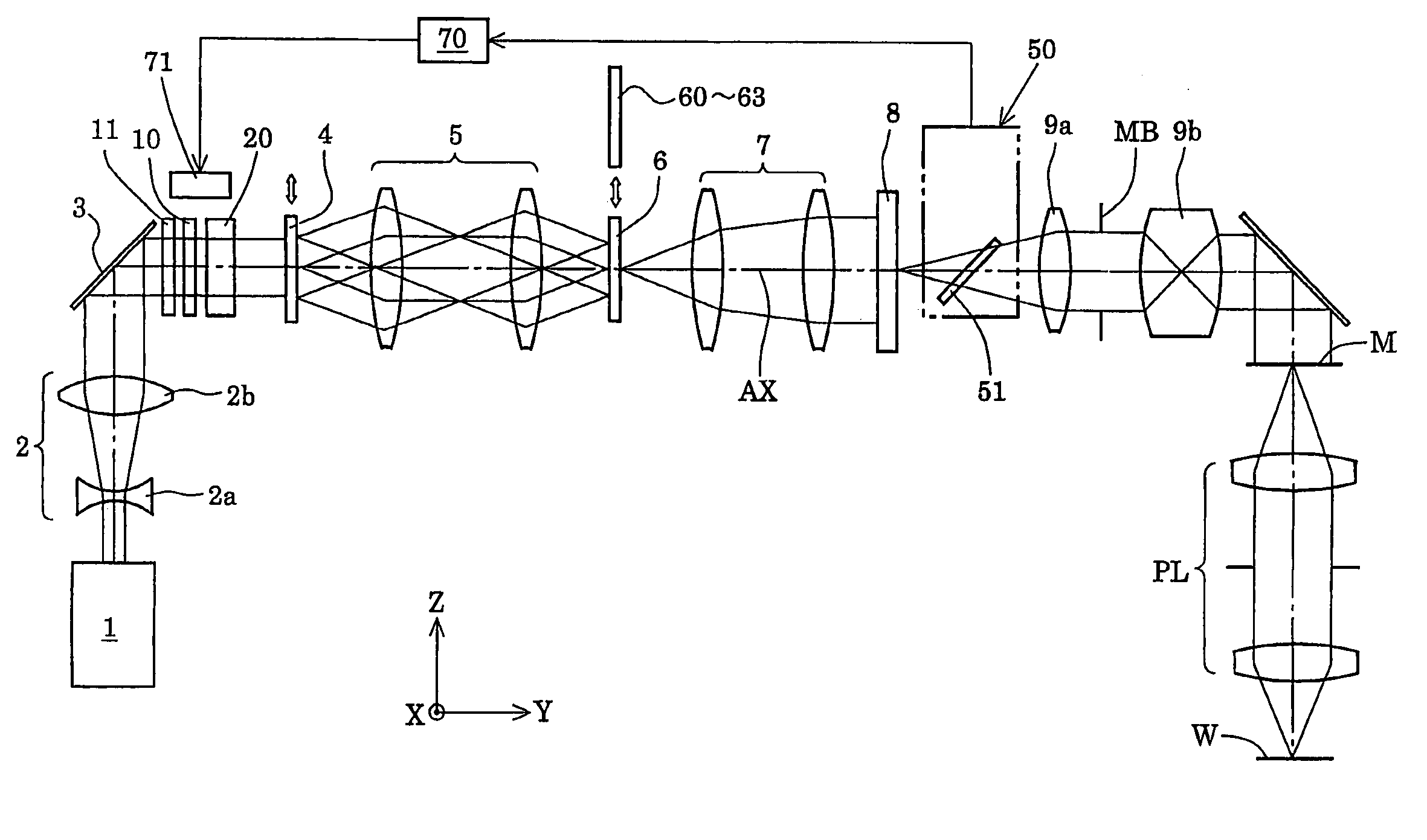
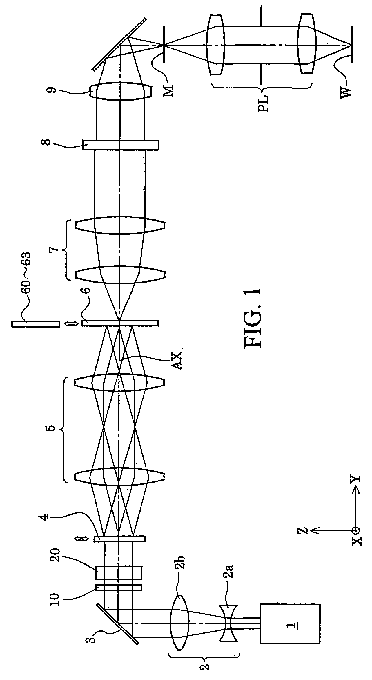
[0044] an illumination optical system that has a light source for providing linearly polarized light and that illuminates an illuminated surface with the light from the light source includes a polarized state switching device that is positioned in a light path between the light source and the illuminated surface and that switches the polarized state of the light that illuminates the illuminated surface between a predetermined polarized state and a nonpolarized state.

[0045] The polarized state switching device is insertable into and removable from an illumination light path and includes a depolarizer that selectively unpolarizes the incident linearly polarized light.

[0046] According to the first embodiment, the polarized state switching device varies a polarization plane of the linearly polarized light if the predetermined polarized state is a linearly polarized state. In addition, it is preferable that the polarized state switching device includes a phase member for selectively ch...

second embodiment

[0057] In a second embodiment, an illumination optical system that illuminates an illuminated surface under a predetermined polarized state with light from a light source includes a light directing device that directs the light from the light source to the illuminated surface and is positioned in a light path between the light source and the illuminated surface, and a polarized state fluctuation correcting device that corrects fluctuations in the polarized state on the illuminated surface and is positioned in the light path between the light source and the illuminated surface.

[0058] According to the second embodiment, the polarized state fluctuation correcting device includes a polarized state adjusting device that adjusts the polarized state on the illuminated surface and is positioned in the light path between the light source and the illuminated surface, a polarization monitor that detects the polarized state of the light and is positioned in the light path between the light sour...

third embodiment

[0059] In a third embodiment, an illumination optical system that illuminates an illuminated surface with light from a light source includes a light directing device that directs the light from the light source to the illuminated surface and is positioned in a light path between the light source and the illuminated surface, and a polarized state stabilizing device that stabilizes the polarized state on the illuminated surface and is positioned in the light path between the light source and the illuminated surface.

[0060] According to the third embodiment, the polarized state stabilizing device includes a polarized state adjusting device that adjusts the polarized state on the illuminated surface and is positioned in the light path between the light source and the illuminated surface, a polarization monitor that detects the polarized state of the light and is positioned in the light path between the light source and the illuminated surface, and a controller that controls the polarized...


PUM

PropertyMeasurementUnit
wavelengthaaaaaaaaaa
angleaaaaaaaaaa

Abstract

An illumination optical system for, when installed in an exposure system, realizing a suitable illumination condition by varying the polarized state of the illumination light according to the pattern characteristics of the mask while suppressing the loss of the intensity of the light. The illumination optical system has a light source unit for supplying a linearly polarized light for illuminating surfaces to be illuminated therewith, and a polarized state changing device for changing the polarized state of the illuminating light from a predetermined polarized state to a nonpolarized state and vice versa. The polarized state changing device is arranged in the optical path between the light source unit and the surfaces to be illuminated. The polarized state changing device can be removed from the illumination optical path and has a depolarizer for selectively depolarizing the incident linearly polarized light.

Description

RELATED APPLICATIONS [0001] This is a Continuation-In-Part of International Application No. PCT / JP03 / 015447 filed Dec. 2, 2003. The entire disclosure of said International Application No. PCT / JP03 / 015447 is incorporated by reference herein in its entirety. The disclosure of each of the following priority applications is herein incorporated by reference in its entirety: Japanese Patent Application No. 2002-351186 filed Dec. 3, 2002; Japanese Patent Application No. 2003-201079 filed Jul. 24, 2003; and Japanese Patent Application No. 2003-338447 filed Sep. 29, 2003.BACKGROUND [0002] This invention relates to illumination optical systems, exposure apparatus and exposure methods. In particular, this invention relates to exposure apparatus for manufacturing micro devices, such as semiconductor elements, imaging elements, flat panel displays such as liquid crystal display elements and thin-film magnetic heads, using lithographic processes. [0003] In typical exposure apparatus of this type,...

Claims


Application Information

Patent Timeline
Patent Type & Authority Applications(United States)
IPC IPC(8): G02F1/1335G03F7/20
CPCG03B27/42G03F7/70566G03F7/70091G03F7/70191G03F7/70558
Inventor TANITSU, OSAMUTANAKA, HIROHISAMURAMATSU, KENICHIKOMINE, NORIONISHINAGA, HISASHIMATSUYAMA, TOMOYUKIKUDO, TAKEHITO
Owner NIKON CORP
Why Eureka
Try Eureka