Apparatus and method of monitoring operating parameters of a gas turbine

a gas turbine and operating environment technology, applied in the field of operating environment monitoring parameters of gas turbines, can solve the problems of difficult to obtain real-world operating environment data, designers and operators have very little information regarding the internal status of turbine engine components during operation, and superalloy materials cannot withstand extended exposure to the hot combustion gas of the current generation gas turbine engine withou

Inactive Publication Date: 2006-03-16
SIEMENS ENERGY INC
View PDF43 Cites 121 Cited by
  • Summary
  • Abstract
  • Description
  • Claims
  • Application Information

AI Technical Summary

Problems solved by technology

However, even superalloy materials are not able to withstand extended exposure to the hot combustion gas of a current generation gas turbine engine without some form of cooling and/or thermal insulation.
Such real world operating environment data is very difficult to obtain, particularly for components that move during the operation of the engine, such as the rotating blades of the turbine.
Despite the extreme sophistication of modem turbine engines, such as gas turbines for generating electrical power or aircraft engines for commercial and military use, designers and operators have very little information regarding the internal status of the turbine engine components during operation.
This is due to the harsh operating conditions, which have prevented the use of traditional sensors for collecting reliable information of critical engine components.
The lack of specific component information makes early failure detection very difficult, often with the consequence of catastrophic engine failure due to abrupt part failure.
This results in inefficient utilization, unnecessary downtime and an enormous increase in operating cost.
This approach is highly subjective and only allows for determining already severe situations with an engine.
It does not provide indications of impending damage or insight into the progression of events leading up to and causing engine damage due to component degradation or failure.
Instrumenting components using this technique is expensive, which is a barrier to instrumenting a large number of components within a single turbine.
Further, the wire leads and data transfer is frequently poor, which can result in costly repairs and flawed data analysis.
Using thermocoup...

Method used


Image

  • Apparatus and method of monitoring operating parameters of a gas turbine
  • Apparatus and method of monitoring operating parameters of a gas turbine
  • Apparatus and method of monitoring operating parameters of a gas turbine

Examples


Embodiment Construction

[0031] Embodiments of the present invention may use microelectromechanical systems (MEMS) devices as sensors embedded within various types of coatings recognized by those skilled in the art. For example, barrier coating may be used herein generally to refer to a range of coatings commonly used in combustion turbine engines such as abradable coating systems, thermal barrier coatings, CMC coatings, wear coatings, protective overlay coatings, insulating coatings and restoration coatings as well as others. Reference to specific types of coatings herein is by way of example only.

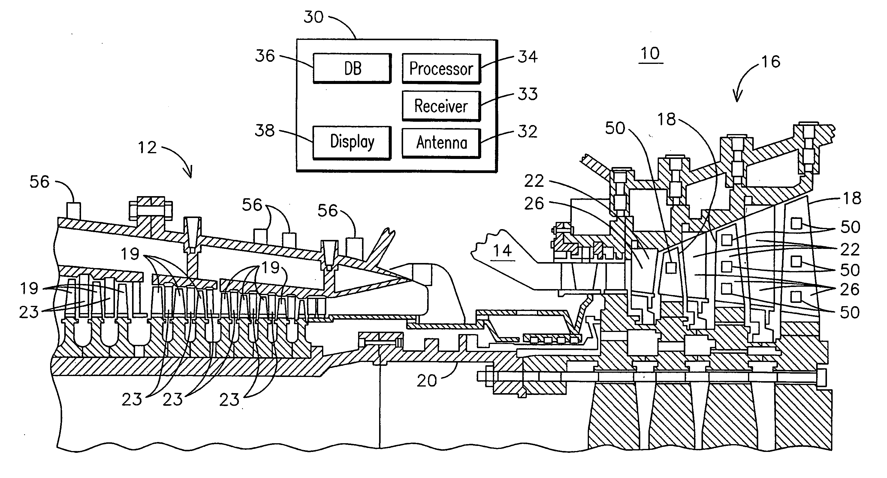
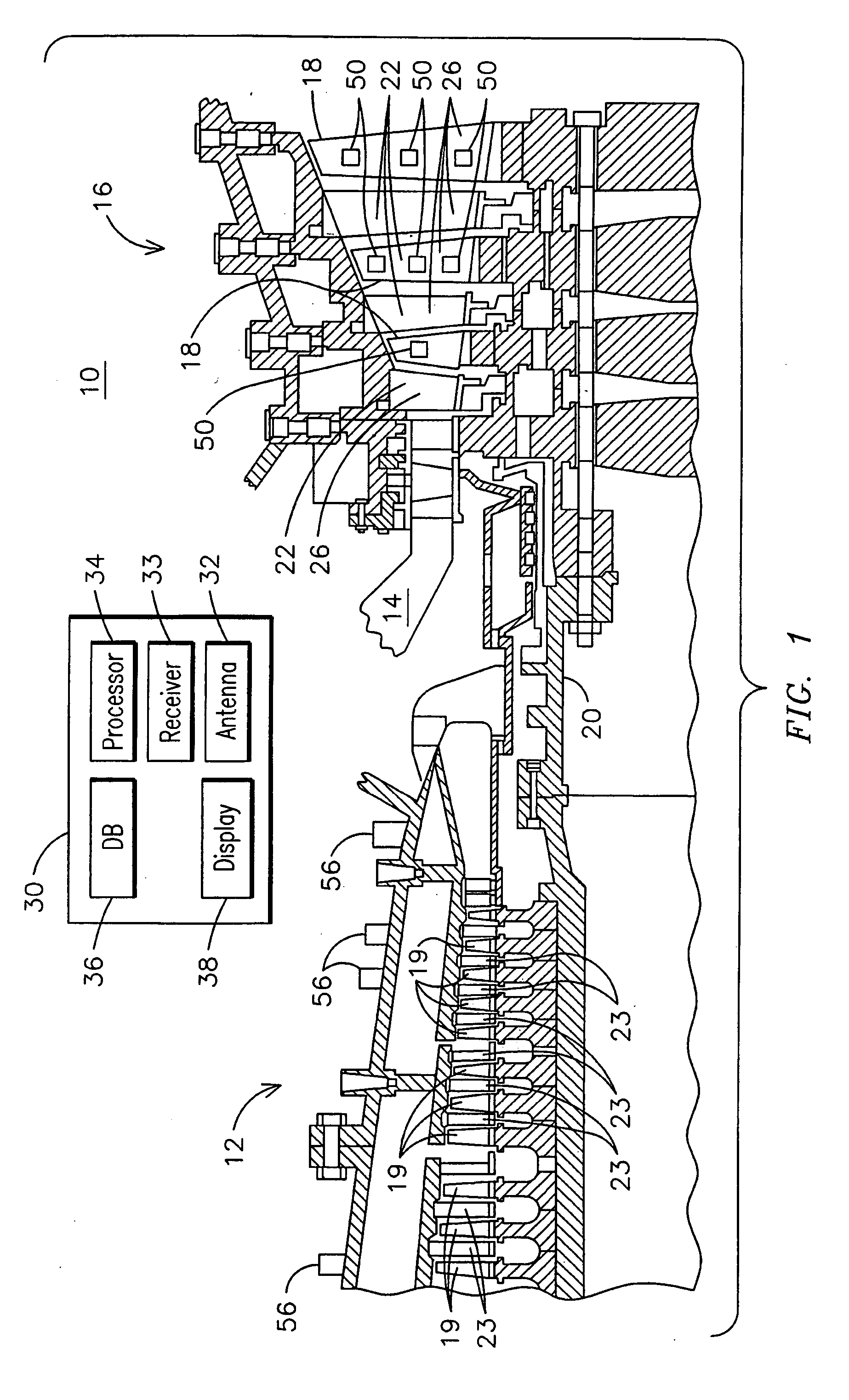
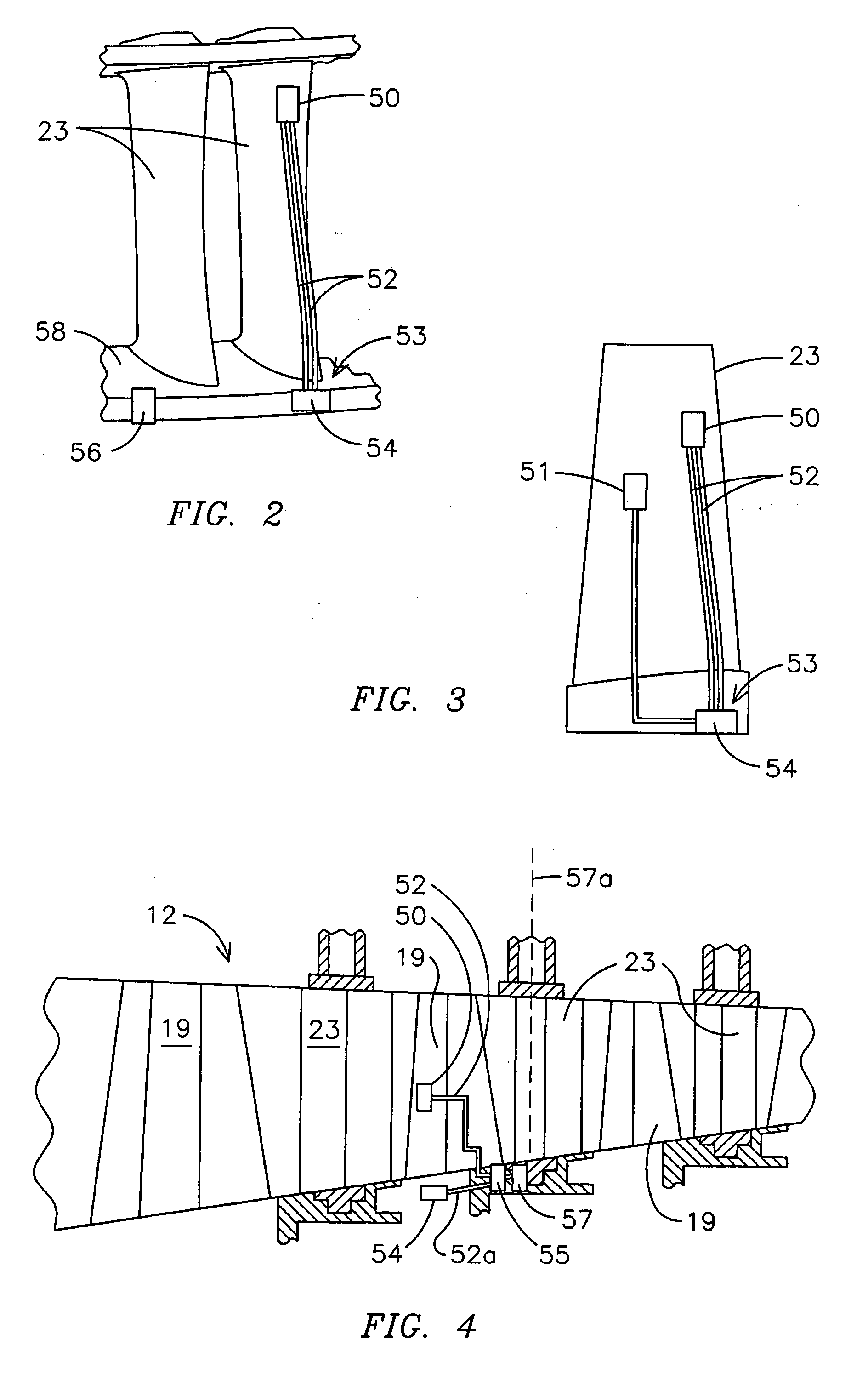
[0032] MEMS devices may be embedded in barrier coatings and / or affixed on or within a surface of components to enable monitoring and diagnostics of a system such as an exemplary combustion turbine 10 of FIG. 1. Using MEMS devices is advantageous because they may be placed directly at locations of interest due to their small size and robust electrical connections. Locating MEMS devices directly at locations of in...


PUM

PropertyMeasurementUnit
Forceaaaaaaaaaa
Depthaaaaaaaaaa
Thermal propertiesaaaaaaaaaa

Abstract

A component for use in a combustion turbine (10) is provided that includes a substrate (212) and a microelectromechanical system (MEMS) device (50, 250) affixed to the substrate (212). At least one connector (52) may be deposited in electrical communication with the MEMS device (50, 250) for routing a data signal from the MEMS device (50, 250) to a termination location (59). A barrier coating (216) may be deposited on the substrate (212) wherein the MEMS device (50, 250) is affixed beneath a surface of the barrier coating (216). A plurality of trenches (142) may be formed in the barrier coating (216) at respective different depths below the surface of the barrier coating (216) and a MEMS device (50, 250) deposited within each of the plurality of trenches (142). A monitoring system (30) is provided that may include a processing module (34) programmed for receiving data from the MEMS device (50, 250).

Description

CROSS REFERENCE TO RELATED APPLICATIONS [0001] This application is a continuation-in-part of pending U.S. patent application Ser. No. 11 / 122,566 filed May 5, 2005, which claims the benefit of Provisional Patent Application No. 60 / 581,662 filed on Jun. 21, 2004, which is also a continuation-in-part of pending U.S. patent application Ser. No. 11 / 018,816 filed Dec. 20, 2004, which is a continuation-in-part of U.S. patent application Ser. No. 10 / 252,236 filed Sep. 23, 2002, now U.S. Pat. No. 6,838,157 all of which are incorporated herein by reference.FIELD OF THE INVENTION [0002] The present invention relates generally to monitoring parameters of operating environments and particularly to an apparatus and method of determining wear behavior of an abradable coating system deposited on components within an operating environment such as a gas turbine engine. BACKGROUND OF THE INVENTION [0003] Gas combustion turbines are used for a variety of applications such as driving an electric generat...

Claims


Application Information

Patent Timeline
IPC IPC(8): F04D29/00B32B9/04F01D17/02F01D17/08F01D21/00
CPCF01D17/02F01D17/08F05D2230/30F05D2230/90F05D2260/80F01D21/003B33Y80/00
Inventor SABOL, STEPHEN M.SUBRAMANIAN, RAMESHKULKARNI, ANAND A.
Owner SIEMENS ENERGY INC
Why Eureka
Try Eureka