Control valve assembly for controlling gas flow in gas combustion systems

a gas combustion system and control valve technology, applied in combustion control, household stoves or ranges, gaseous heating fuels, etc., can solve the problems of difficult packaging and integration of small size chips of mems devices as a part of a macro scale system, and the design of such systems is difficul

Inactive Publication Date: 2006-03-16
GENERAL ELECTRIC CO
View PDF8 Cites 31 Cited by
  • Summary
  • Abstract
  • Description
  • Claims
  • Application Information

AI Technical Summary

Problems solved by technology

However, designing such systems is challenging due to large actuation displacement requirements that are required for such systems as a large cross section area may be required in the flow circuit to accommodate high levels of flow.
Further, it is difficult to achieve large actuation displacements with a small MEMS device.
In systems where MEMS devices are employed for the gas flow control, it may be difficult to package and integrate a small size chip of the MEMS device as a part of a macro scale system.
In addition, heat generated by an electrothermal actuator of the MEMS device during actuation may cause device failure.
Incorporation of individual calibration of the electrothermal actuators is a challenge due to costs and added complexity involved in such calibration arrangements.

Method used


Image

  • Control valve assembly for controlling gas flow in gas combustion systems
  • Control valve assembly for controlling gas flow in gas combustion systems
  • Control valve assembly for controlling gas flow in gas combustion systems

Examples


Embodiment Construction

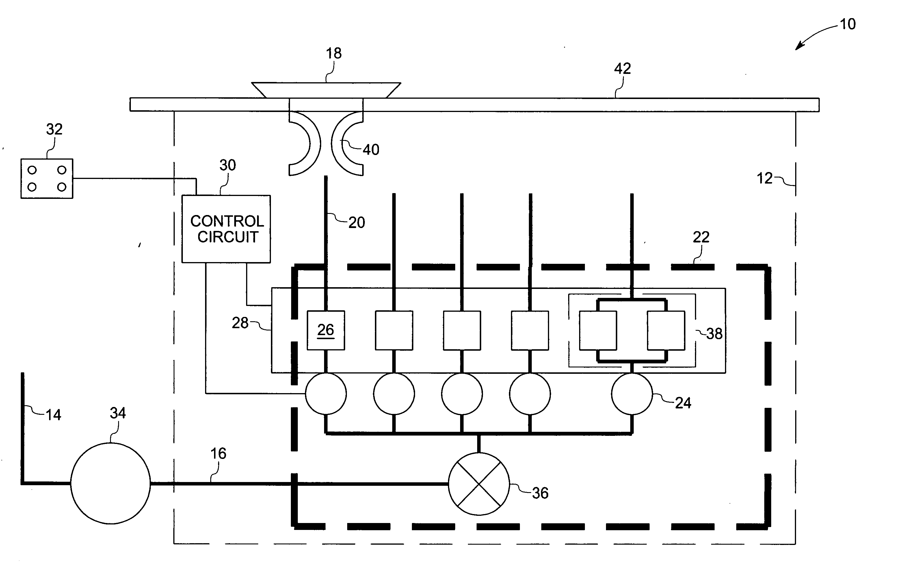
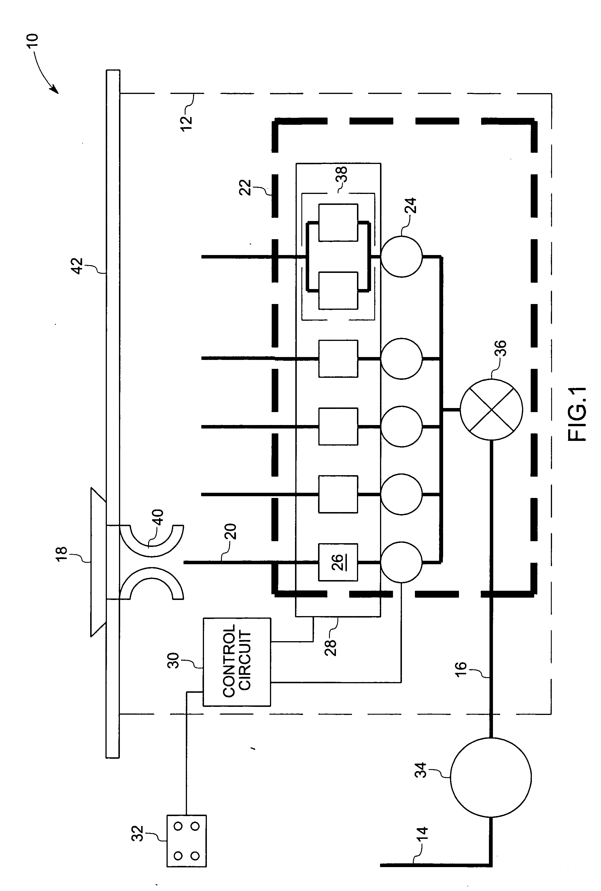
[0021]FIG. 1 illustrates a gas burner system 10 with a control valve assembly, according to an embodiment, for use in a gas operated cooking appliance, such as, but not limited to, gas stove, gas hobs, and gas ovens. In the embodiment illustrated in FIG. 1, the gas burner system 10 includes a series of components disposed in a housing 12. In a presently contemplated configuration, the gas burner system 10 receives a gas flow from a supply 14 via an inlet 16 and the gas flow is delivered to a gas burner 18 via an outlet 20 for use in various cooking activities. A valve assembly 22 with a positive-shutoff valve 24 and a micro electromechanical system (MEMS) valve 26 is coupled between the inlet 16 and the outlet 20 for regulating the gas flow from the inlet 16 to the outlet 20. It should be noted that, the MEMS valve 26 is coupled in series to the positive-shutoff valve 24. In this embodiment, the positive-shutoff valve 24 is disposed upstream of the MEMS valve 26. Further, the MEMS v...


PUM


Abstract

A control valve assembly includes an inlet for receiving a gas flow and an outlet for providing the gas flow to a gas burner. The assembly also includes a positive-shutoff valve for interrupting the gas flow from the inlet. A micro electromechanical system (MEMS) valve is coupled in series to the positive-shutoff value between the inlet and the outlet for regulating the gas flow from the inlet to the outlet.

Description

BACKGROUND [0001] The invention relates generally to gas combustion systems, and more particularly, to control of gas flow in a gas combustion system. [0002] Various gas combustion systems are known and are generally in use. For example, a gas cooking system receives a flammable gas flow from a supply and this flow of gas is directed to a gas burner of the gas cooking system. Downstream combustion components, such as burners, require large cross-sections in the flow circuit to accommodate flow rates that enable high heat output. [0003] In general, the gas cooking system employs a flow control mechanism, such as a manual mechanical valve, for metering the gas flow from the supply to the gas burner. Certain other natural gas combustion systems employ electronic control via solenoid actuated valves to regulate large flows of gas. Such systems employ either a single continuously variable solenoid valve, or a series of on / off solenoid valves to regulate the flow. [0004] Certain other nat...

Claims


Application Information

Patent Timeline
Patent Type & Authority Applications(United States)
IPC IPC(8): F23Q9/08F24C3/00
CPCF23C2900/03001F23N1/005F24C3/12F23N2037/02F23N2041/08F23N2035/18F23N2235/18F23N2237/02F23N2241/08
Inventor SAIA, RICHARD JOSEPHNAJEWICZ, DAVID JOSEPHSEELEY, CHARLES ERKLINWU, GUANGHUAKNOBLOCH, AARON JAY
Owner GENERAL ELECTRIC CO
Why Eureka
Try Eureka