
Decompression-compensating instrument for ocular surgery, instrument for ocular surgery provided with same and method of ocular surgery

a technology of compensating instruments and ocular surgery, which is applied in the field of compensating instruments for ocular surgery, can solve the problems of adverse effects, further destruction of the posterior chamber, and damage to the corneal endothelium, and achieve the effect of reliably reducing the pressure in the anterior chamber

Active Publication Date: 2006-03-16
MAKOTO KISHIMOTO +2
View PDF8 Cites 12 Cited by
  • Summary
  • Abstract
  • Description
  • Claims
  • Application Information

AI Technical Summary

Benefits of technology

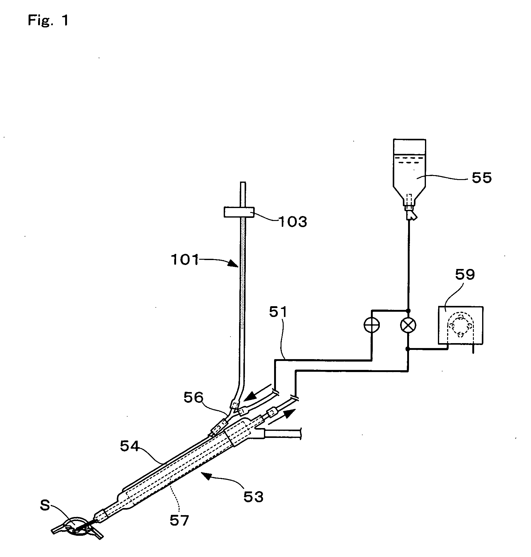
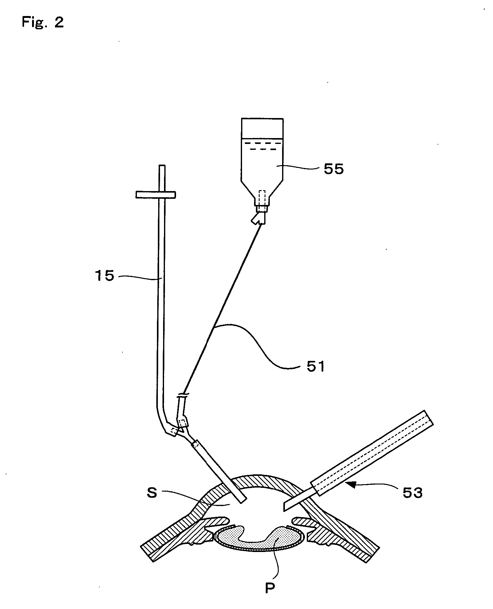
[0017] The present inventor conducted extensive research to achieve the above object and found that the decrease in the pressure in the anterior chamber can be reliably reduced by connecting a decompression-compensating instrument comprising a storage member having a predetermined capacity to a point midway along the supply channel that supplies the perfusate to the affected part.
[0019] According to the decompression-compensating instrument of the present invention, because the storage member having a capacity of 7 cm3 to 22 cm3 is connected to a point midway along the supply channel that supplies the perfusate to the affected part of the eye, the perfusate is supplied from the storage member when the surge occurs, and therefore it is possible to prevent a rapid decrease in the inflow rate (pressure) caused by a loss of balance between the inflow rate (pressure) of the perfusate and the aspiration rate (pressure). Accordingly, it is possible to reliably prevent the decrease of the pressure in the affected part of the eye when the surge occurs.
[0025] Because this intraocular surgical apparatus is provided with the above-described decompression-compensating instrument, it is possible to alleviate the decrease in the pressure of the intraocular affected part when a surge occurs during surgery for treatment of cataracts, etc. Furthermore, because the surgical instrument is integrated with the decompression-compensating instrument, it is easer to use during surgery.

Problems solved by technology

However, this apparatus has the following problems.
This adversely affects the balance between the inflow rate (pressure) and aspiration rate (pressure) of the perfusate, and the anterior chamber becomes unstable.
This causes a so-called microcollapse in which the internal capacity of the eyeball and anterior chamber decreases, which may cause further destruction of the posterior chamber and damage to the corneal endothelium.
Therefore, it was not easy for inexperienced surgeons to cope with this problem.
However, because the surge occurs instantaneously for a short time of less than about 0.2 second, it is difficult in practical terms to suppress the surge without any time lag using these apparatuses.
However, because in intraocular operations such as cataract surgery, very precise and delicate manipulation is required, if the chamber is located at a position 6 to 10 cm from the tip of the handpiece as mentioned above, the motion of the hands operating the handpiece is restricted and this interferes with the surgery.
This may cause the airspace in the chamber to move toward the irrigation inflow hole (the portion connected to the irrigation inflow line).
This not only prevents the irrigation fluid from being promptly supplied but also raises the possibility that air may flow into the eyeball, which may cause additional damage to the intraocular tissues that is different from that caused by the surge.
Furthermore, because it is difficult to mount the chamber near the handpiece, depending on the motion of the chamber, the irrigation supply tube that composes the irrigation supply line may be strongly twisted.
This would prevent the irrigation fluid from being supplied to the eye and may cause the anterior chamber to collapse due to strong aspiration pressure and lead to a serious accident.
However, this publication discloses that it is preferable that the perfusate reservoir be located near the handpiece, and this may cause the same kind of problem as described above for the chamber.
When they tried to discharge the air in the perfusate reservoir by pressing the piston, not only could the air not be discharged from the air inlet hole but the piston could not even be pushed down.
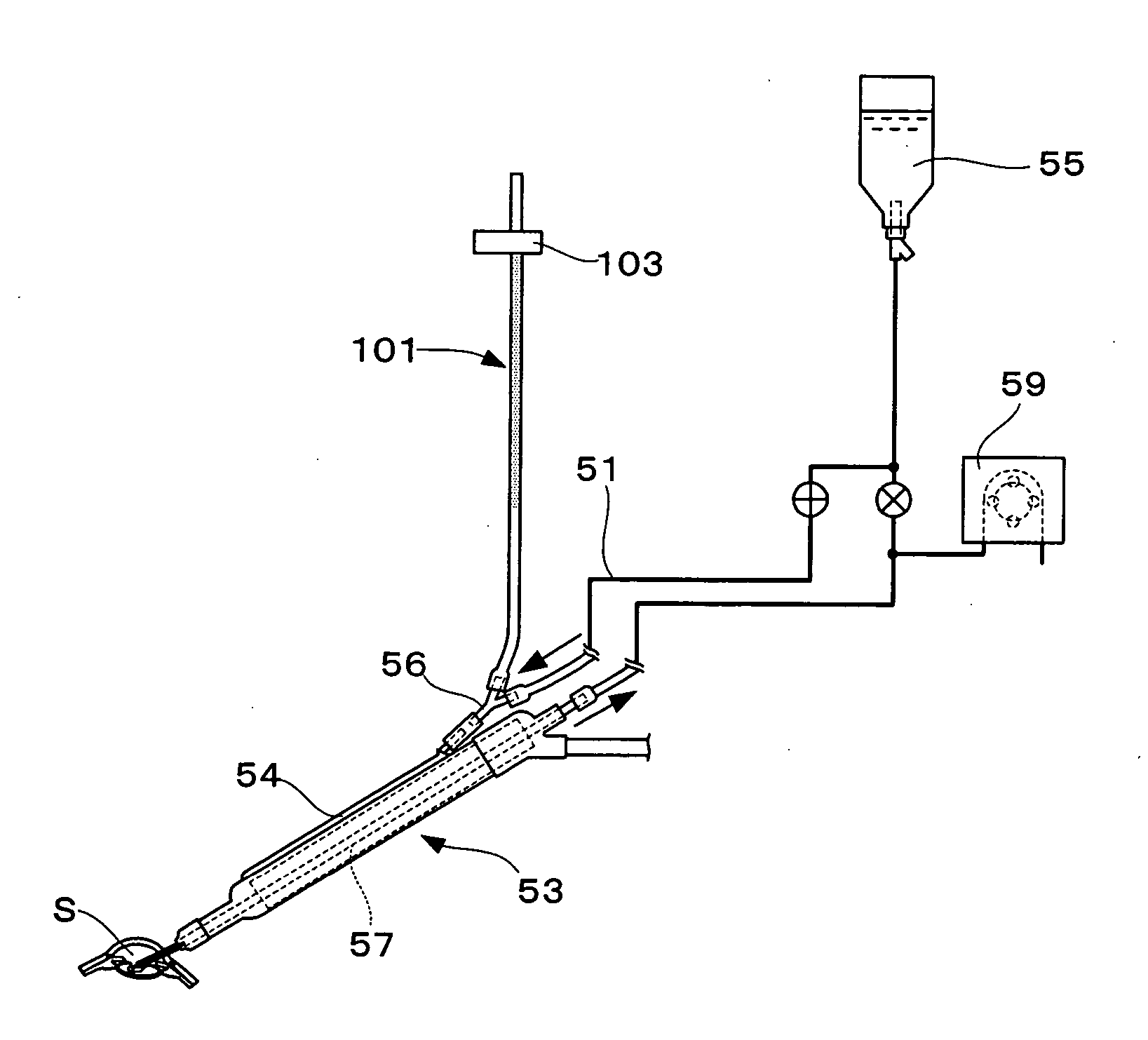
Although the aspiration pump 59 keeps aspirating the perfusate, the amount of perfusate in the aspiration channel gradually decreases because of the blockage thereof, resulting in a rapid increase of the negative pressure in the aspiration channel.
However, depending on the capacity of the tube, etc., when the inflow of the perfusate changes from the tube to the supply tube, the inflow does not switch smoothly.
When such a phenomenon occurs, the inflow of the perfusate to the anterior chamber sometimes cannot adequately cope with the surge and the decrease of the pressure in the anterior chamber may not be reliably alleviated.

Method used


Image

  • Decompression-compensating instrument for ocular surgery, instrument for ocular surgery provided with same and method of ocular surgery
  • Decompression-compensating instrument for ocular surgery, instrument for ocular surgery provided with same and method of ocular surgery
  • Decompression-compensating instrument for ocular surgery, instrument for ocular surgery provided with same and method of ocular surgery

Examples


example

[0078] Hereunder, details of experiments conducted with the present invention are explained with reference to the drawings to further clarify the features of the present invention. FIG. 6 is a drawing schematically showing the structure of the experimental apparatus.

[0079] The capacity of the tube is explained below.

experiment 1

(a) Experiment 1

[0080] Focusing on the fact that the pressure in the anterior chamber during a surge changes in accordance with the pressure in the tube, experiments were conducted in which the capacity of the tube was varied. As shown in FIG. 6, the experimental apparatus used here comprises a handpiece 11, which is a phacoemulsification and aspiration device, and a perfusate bottle 13, which stores the perfusate, connected to the handpiece 11. The handpiece 11 is a piezoelectric, small phaco handpiece manufactured by AMO, which incorporates an inlet channel 17 for supplying the perfusate to the intraocular anterior chamber and an aspiration channel (not shown) through which the perfusate aspirated from the anterior chamber is sent. A cataract surgical device 27 is connected to the rear end portion of the aspiration channel via an aspiration tube 29. This surgical device 27 aspirates perfusate at a predetermined aspiration pressure. In this experiment, a “Series 2000 LEGACY ®” ultr...

experiment 1-1

[0085] The experiment method is described next. A perfusate was supplied to the perfusate tube 15 so as to compress the air in the tube 15. General perfusion was then conducted by setting the aspiration flow rate of the cataract surgical device 27 at 30 cc / min and the maximum aspiration pressure at 200 mmHg. After blocking the aspiration tube 29 with a clamp, the aspiration tube 29 was opened and the change in the pressure of the mock anterior chamber 31 was then measured. This change was defined as the change in pressure during the surge. FIG. 7 shows the results. In FIG. 7, the longitudinal axis indicates the pressure of the mock anterior chamber 31 during the surge, and the horizontal axis indicates the length of the tube 15. As is clear from FIG. 7, when the length of the tube was 60 cm or more, the pressure during the surge did not become negative, and when the length of the tube was 100 cm or more, the tube 15, which serves as a decompression-compensating instrument, operated ...


PUM


Abstract

The present invention relates to a decompression-compensating instrument for use in intraocular surgery, wherein a perfusate is supplied to an affected part of an eye via a supply channel at a predetermined pressure, and the perfusate is aspirated via an aspiration channel together with the affected tissues that are to be removed, the decompression-compensating instrument supplying the perfusate into the affected part when the internal pressure of the affected part is excessively lowered, and being constructed so as to be connectable to a point midway along the supply channel and comprising a storage-member that forms a chamber that is closable except for an opening from which the perfusate to be supplied to the supply channel flows, the capacity of the storage member being 7 cm3 to 22 cm3.

Description

TECHNICAL FIELD [0001] The present invention relates to a decompression-compensating instrument for use in intraocular surgery for treating cataracts, etc., wherein a perfusate is supplied to an affected part in the eye via a supply channel at a predetermined pressure, and the perfusate is aspirated via an aspiration channel together with the tissues in the affected part that are to be removed, the decompression-compensating instrument supplying the perfusate into the affected part when the internal pressure of the affected part is excessively lowered; an instrument for use in ocular surgery provided with the same; and a method of ocular surgery. BACKGROUND ART [0002] In recent years, eye diseases such as cataracts are often treated with an operation that replaces the affected crystalline lens in the eye with an intraocular lens (an artificial crystalline lens). Phacoemulsification and aspiration (PEA) is widely employed in such a surgical operation wherein the affected crystalline ...

Claims


Application Information

Patent Timeline
Patent Type & Authority Applications(United States)
IPC IPC(8): A61F9/00A61F9/007A61M1/00
CPCA61F9/00736A61M1/0058A61M1/0031A61M1/74A61M2210/0612A61M1/77
Inventor KISHIMOTO, MAKOTOKIMURA, YOSHIYUKI
Owner MAKOTO KISHIMOTO
Learn More