Transmission for a walk-behind lawn mower

a technology for walking behind and mowers, applied in the field of transmissions, can solve the problems of increasing the cost of mowers, and complicated parts, and achieve the effects of less space, economic manufacturing, and convenient control of the transmission

Active Publication Date: 2006-03-23
MTD PRODUCTS
View PDF8 Cites 36 Cited by
  • Summary
  • Abstract
  • Description
  • Claims
  • Application Information

AI Technical Summary

Benefits of technology

[0007] The present invention provides a variable speed transmission which overcomes the disadvantages of prior transmissions and / or speed controls by providing an inexpensive variable speed transmission that is economical to manufacture and requires less space. Additionally, a clutch mechanism is provided on the transmission for clutching and declutching the transmission. Furthermore, the operator need only move the pivot arm of the transmission to cause a change in the speed of the transmission, thereby providing ease of control of the transmission.

Problems solved by technology

These designs constitute pieces that are complicated to produce and of relatively high cost.
Additionally, these systems generally require more space and greater number of parts, which increase the mower cost since the systems require more expensive production and assembly operations.

Method used


Image

  • Transmission for a walk-behind lawn mower
  • Transmission for a walk-behind lawn mower
  • Transmission for a walk-behind lawn mower

Examples


Embodiment Construction

[0024] The invention will now be described in the following detailed description with reference to the drawings, wherein preferred embodiments are described in detail to enable practice of the invention. Although the invention is described with reference to these specific preferred embodiments, it will be understood that the invention is not limited to these preferred embodiments. But to the contrary, the invention includes numerous alternatives, modifications and equivalents as will become apparent from consideration of the following detailed description.

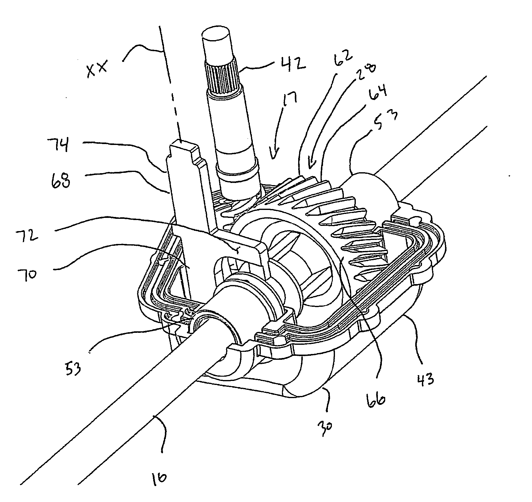
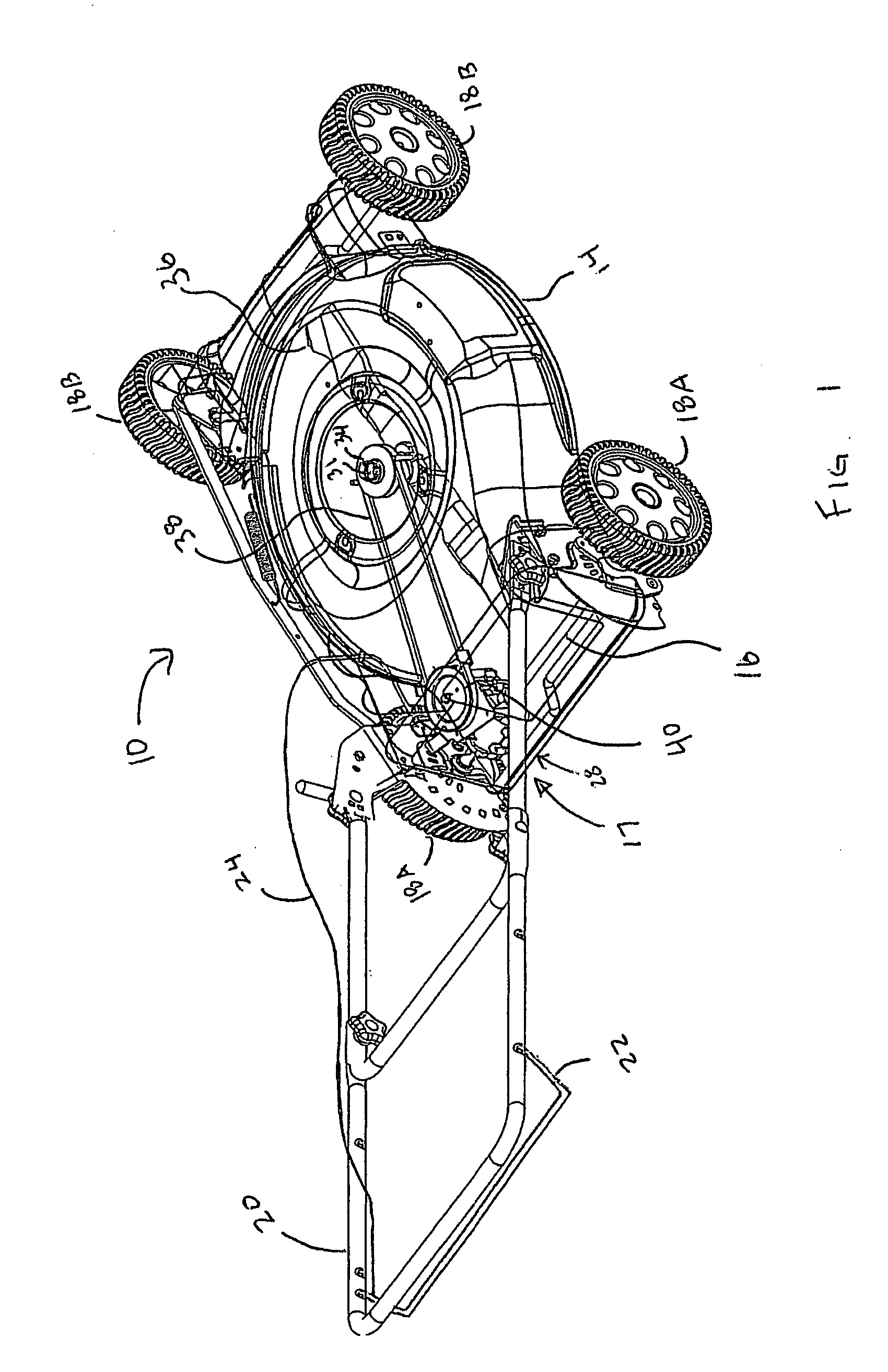
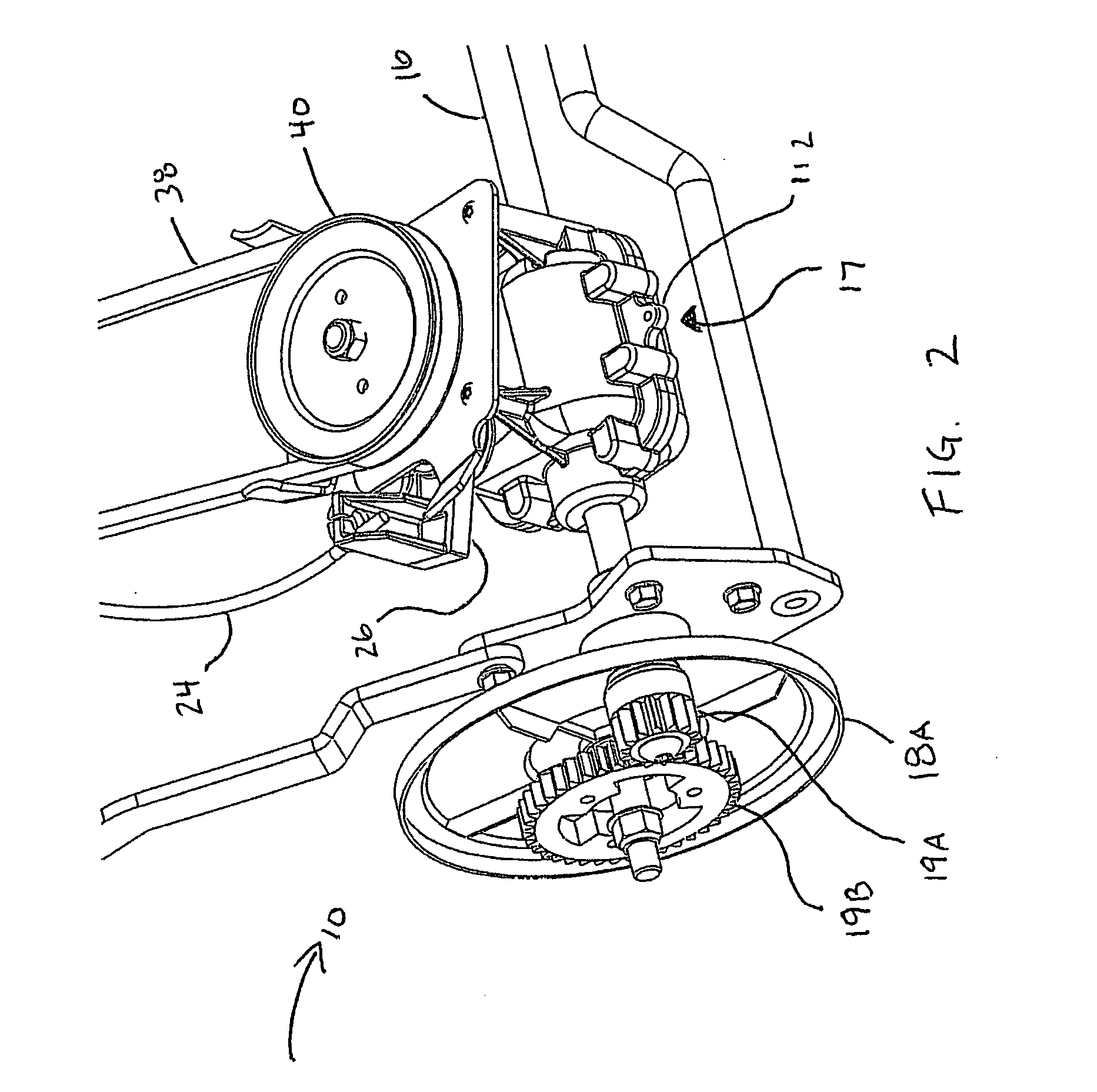
[0025] Referring first to FIGS. 1-3, a self-propelled lawnmower, broadly a self-propelled machine, is shown generally at 10 having engine (not shown to improve clarity) mounted on deck 14. Although the current invention is shown in an embodiment describing a lawnmower, the invention could equally as well be used with other self-propelled machines such as yard vacuums, snow throwers, tillers and the like. An axle 16 is rotatably mo...


PUM


Abstract

A transmission device between a primary motor shaft and a drive shaft for the wheels of self-propelled lawn mowers having a driving member connectable to a motor shaft, an output shaft, and a helically threaded driven gear rotatably mounted and moveable axially on the output shaft, the driven gear including an exterior driving surface and an interior surface, the interior surface including a plurality of teeth fixed in rotation with the gear, the teeth having a sloped leading edge and trailing edges substantially on a plane extending radially outward from the center of the driven gear, the outer engaging surface in constant engagement with the driving member so that the driven gear rotates whenever the driving member rotates. A control member configured to move the driven gear along the axial axis of the output shaft from a first position to a second position, the control member including a fork with two branches, each branch of the fork being provided with a radial internal tooth so as to ensure contact with the driven gear. A projection secured in rotation with the output shaft and extending from the output shaft such that opposite ends of the projection project from the output shaft to engage the interior teeth of the driven gear, projection being positioned on the output shaft such that when the driven gear is in the first position, the projection is disengaged from the interior surface of the driven gear such that the driven gear is uncoupled from the output shaft, and when the driven gear is moved to the second position, the projection engages the interior surface of the driven gear in a locking relationship to produce a driving rotation of the output shaft.

Description

BACKGROUND OF THE INVENTION [0001] 1. Field of Invention [0002] This invention relates to transmissions, and more particularly adapted to a transmission device between a primary motor shaft and an output drive shaft connected to the wheels of a self-propelled lawn mower. [0003] 2. Description of Related Art [0004] It is known in the art to use variable speed transmission assemblies on self-propelled walk-behind lawn mowers to permit the ground speed of the mower to be varied while maintaining a constant engine speed. A constant engine speed is desirable because it facilitates, for example, effective cutting by the lawnmower mower blade. [0005] Previous variable speed transmission designs have incorporated various gear arrangements or multiple drive belt and multiple pulley systems to propel the lawn mower or tractor while still maintaining a constant engine speed. For example, some planetary gear arrangements include a series of intermeshed gears to provide a suitable mower axle spe...

Claims


Application Information

Patent Timeline
Patent Type & Authority Applications(United States)
IPC IPC(8): F16H3/38
CPCA01D34/69A01D2101/00Y10T74/19288F16H1/16Y10T74/19219F16D11/10
Inventor RUEBUSCH, RICHARD THOMASHELIN, PHILIP
Owner MTD PRODUCTS
Why Eureka
Try Eureka