Heat exchanger structure of automatic transmission

a technology of heat exchanger and automatic transmission, which is applied in the direction of lighting and heating apparatus, process and machine control, instruments, etc., can solve the problems of inability to control the switching of the valve based on the temperature of oil flowing into the transmission, the temperature of oil cannot be readily stabilized, and the oil flow is subject to heat exchang

Inactive Publication Date: 2006-03-23
TOYOTA JIDOSHA KK
View PDF10 Cites 30 Cited by
  • Summary
  • Abstract
  • Description
  • Claims
  • Application Information

AI Technical Summary

Benefits of technology

[0009] The present invention is made to solve the problem as described above. An object of the present invention is to provide a heat exchanger structure of an automatic transmission which can stabilize a temperature of oil.

Problems solved by technology

The oil actually flowing into a transmission, however, may be subject to heat exchange by a second heat exchanger.
Therefore, control of switching of the valve based on a temperature of the oil flowing into the transmission may not be possible.
The conventional heat exchanger structure described above has a problem that a temperature of oil cannot be stabilized readily.

Method used


Image

  • Heat exchanger structure of automatic transmission
  • Heat exchanger structure of automatic transmission
  • Heat exchanger structure of automatic transmission

Examples


first embodiment

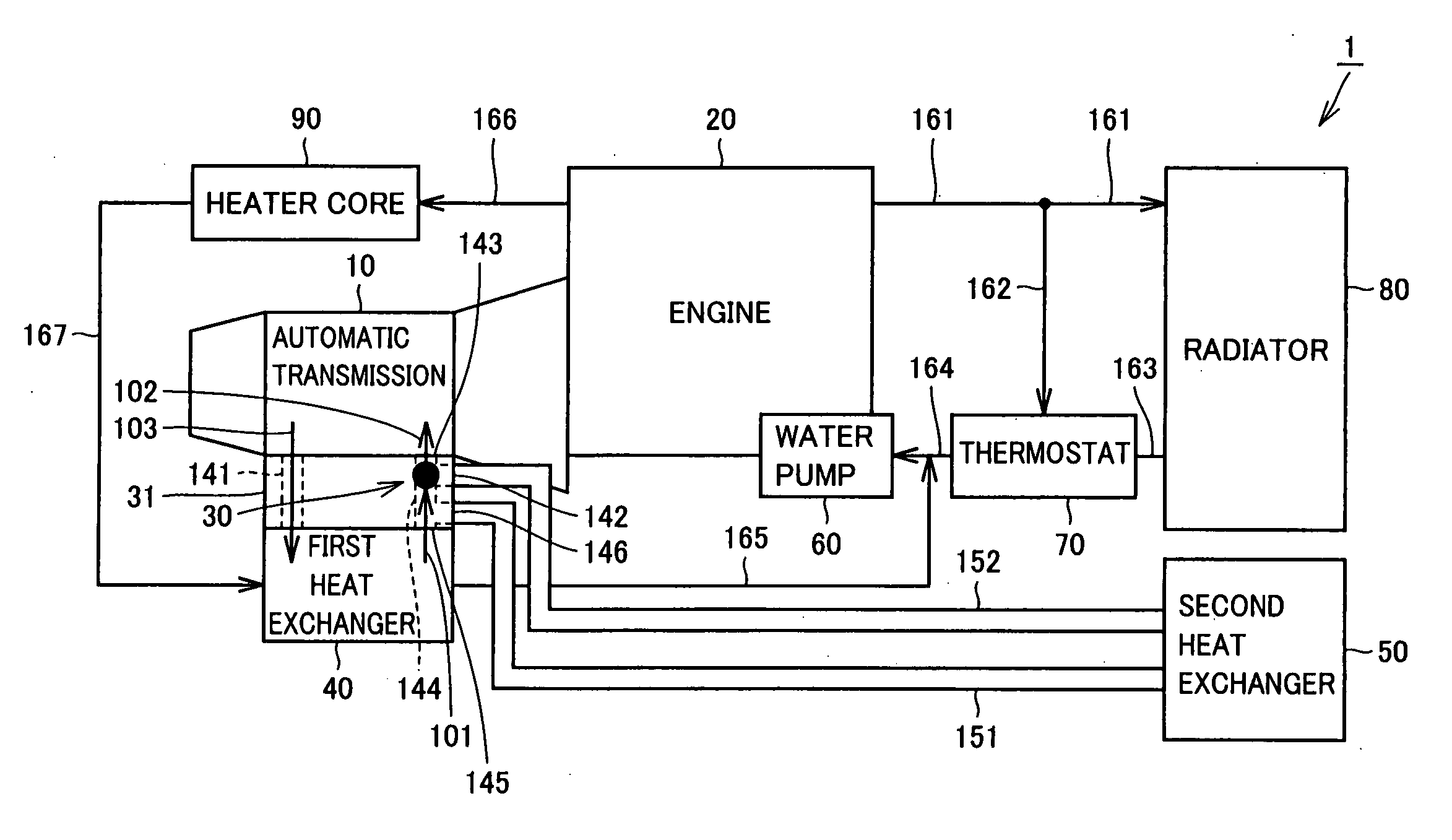
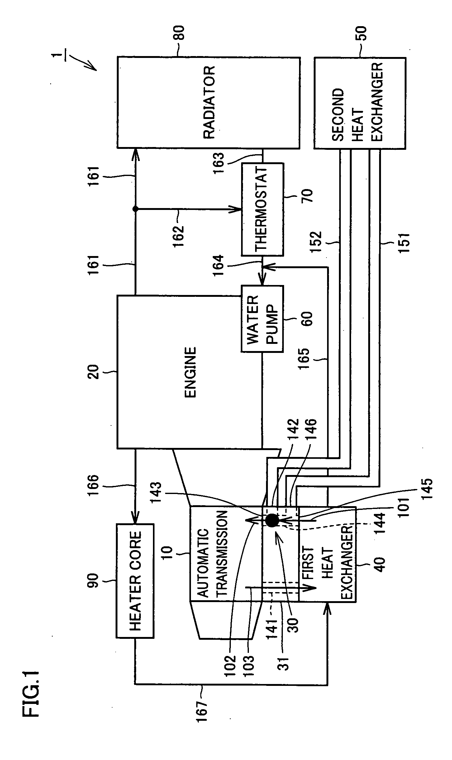
[0026] Referring to FIG. 1, a heat exchanger structure 1 of an automatic transmission according to a first embodiment of the present invention includes an engine 20 for generating power and an automatic transmission 10 which can receive the power from engine 20 and convert a rotation number and a rotational torque of the power. Engine 20 is a source of power, which can be a gasoline engine or a diesel engine. In addition, engine 20 can be formed not only with an internal combustion engine but also with an external combustion engine. Engine 20 can further be formed with a motor / generator.

[0027] Rotational force output from engine 20 is converted with automatic transmission 10. A structure using a torque converter and a planet gear can be adopted as automatic transmission 10. Automatic transmission 10 is not limited to this, and a continuously variable transmission can also be adopted. Automatic transmission 10 can also be formed with a transmission having a plurality of constant mes...

second embodiment

[0060] Referring to FIG. 7, a heat exchanger structure of an automatic transmission according to a second embodiment of the present invention is different from the structure according to the first embodiment in that, thermo valve 30 and first heat exchanger 40 are provided separately from automatic transmission 10. That is, thermo valve 30 is connected to automatic transmission 10 with an oil passage 153, and first heat exchanger 40 is connected to automatic transmission 10 with an oil passage 154.

[0061] The heat exchanger structure of an automatic transmission according to the second embodiment constructed as such also has effects similar to that of the heat exchanger structure according to the first embodiment.

third embodiment

[0062] Referring to FIG. 8, a heat exchanger structure of an automatic transmission according to a third embodiment of the present invention is different from the structure according to the first embodiment in that, heater core 90, water pump 60, thermostat 70, and radiator 80 shown in the first embodiment are not provided. Both of first and second heat exchangers 40, 50 can exchange heat with outside air. It is to be noted that, first and second heat exchangers 40, 50 may be cooled by spraying water onto the heat exchangers 40, 50.

[0063] The heat exchanger structure of an automatic transmission according to the third embodiment constructed as such also has effects similar to that of the structure according to the first embodiment.

[0064] Various modifications of the embodiments of the present invention described above are possible. First, the present invention can be applied not only to an automobile of a so-called length side type in which automatic transmission 10 is arranged or...


PUM


Abstract

A heat exchanger structure of an automatic transmission stabilizing a temperature of oil is provided. A heat exchanger structure of an automatic transmission includes an automatic transmission, a first heat exchanger provided on an upstream side and a second heat exchanger provided on a downstream side, each capable of cooling oil ejected from the automatic transmission, and a thermo valve capable of supplying oil subject to heat exchange by at least one of first and second heat exchangers to the automatic transmission. When a temperature of the oil is relatively low, the thermo valve supplies oil passed through the first heat exchanger to the automatic transmission and shuts off a flow of oil from the second heat exchanger to the automatic transmission. When a temperature of the oil is relatively high, the thermo valve supplies oil passed through first and second heat exchangers to the automatic transmission.

Description

[0001] This nonprovisional application is based on Japanese Patent Application No. 2004-250594 filed with the Japan Patent Office on Aug. 30, 2004, the entire contents of which are hereby incorporated by reference. BACKGROUND OF THE INVENTION [0002] 1. Field of the Invention [0003] The present invention relates to a heat exchanger structure of an automatic transmission and, more specifically, to a heat exchanger structure of an automatic transmission which can stabilize a temperature of oil. [0004] 2. Description of the Background Art [0005] A conventional heat exchanger structure of an automatic transmission is disclosed in, for example, Japanese Patent Laying-Open No. 11-264318 (a patent document 1). [0006] Patent document 1 discloses a structure including two heat exchangers, in which a heat exchange path of oil is switched based on a temperature of oil. [0007] Switching of a switching valve (thermo valve) in a conventional technique is controlled with a temperature of oil subjec...

Claims


Application Information

Patent Timeline
Patent Type & Authority Applications(United States)
IPC IPC(8): B60H1/00G05D23/00F16H57/02F16H57/04
CPCF01P7/165F01P11/08F01P2025/40F01P2060/045F01P2060/08Y10T74/2189F16H57/0415G05D23/022Y10S165/916Y10T74/19991F16H57/0413G05D23/1333
Inventor SASAKI, KAZUMICHI
Owner TOYOTA JIDOSHA KK
Why Eureka
Try Eureka