Technique for subwoofer distance measurement

a technology of distance measurement and subwoofer, which is applied in the direction of measurement devices, instruments, computing, etc., can solve the problems of not always accurately reflecting the peak of the impulse response, the outside control of the manufacturer, and the inability to fine tune the home theater system. , to achieve the effect of increasing the width of the impulse and greatly increasing the accuracy of the computed distan

Active Publication Date: 2006-03-23
CIRRUS LOGIC INC
View PDF7 Cites 20 Cited by
  • Summary
  • Abstract
  • Description
  • Claims
  • Application Information

AI Technical Summary

Benefits of technology

[0019] The present invention automatically corrects for subwoofer or other speaker crossover settings or other parameters by providing an ad justable factor based upon not only pulse location, but on pulse width. In FIG. 2, as the low-pass frequency of the subwoofer is decreased, either by the crossover setting or the physical design of the subwoofer, the impulse response is shifted to the right and the width of the impulse increases. By relating the adjustment factor to the width of the impulse, the accuracy of the computed distance is greatly increased. The relation may be found doing a simple polynomial curve fitting to empirical data from several subwoofers at various crossover settings and distances, storing that data, and then measuring pulse location and width of the actual subwoofer during the setup routine, and adjusting the distance (delay) calculations accordingly.

Problems solved by technology

One problem with such systems is that a major aspect of acoustical sound reproduction may depend upon the relative location of each of the speakers in a room, relative to the preferred listening area, as well as room acoustics, speaker orientation, and the like.
These aspects are largely outside the control of the manufacturer, as speaker placement can only be suggested by the manufacturer, and room configuration or other criteria may alter such placement by the consumer.
In addition, the size of a room in which the system is setup is impossible to predetermine, and thus a great variance results in the placement, orientation, and location of speakers, as well as their relative distance from the preferred listening area.
Unfortunately, hiring an acoustician to fine tune their home theater system is expensive while many “consumer grade” home theater systems sell for only a few hundred dollars, which is far less than the cost of even one in-home visit by an acoustician.
When measuring a subwoofer, however, the peak of the impulse response does not always accurately reflect the distance of the subwoofer from the preferred listening location due to the band-limited response of the speaker.
Additionally, many subwoofers include a built-in low-pass crossover that further alters the impulse response and thus provides an inaccurate distance measurement.
Inaccurate measurement of the subwoofer location hampers proper setup of the home theater system, as the subwoofer sound may not be optimized for the preferred listening location.
In some applications, manufacturers simply ignore the problem, as they have no ready fix.
This approach is obviously not an adequate solution.
Unfortunately, many subwoofers do not allow the crossover to be disabled and / or do not have an adjustable frequency settings.
Obviously, this approach is also very limited.

Method used


Image

  • Technique for subwoofer distance measurement
  • Technique for subwoofer distance measurement
  • Technique for subwoofer distance measurement

Examples


Embodiment Construction

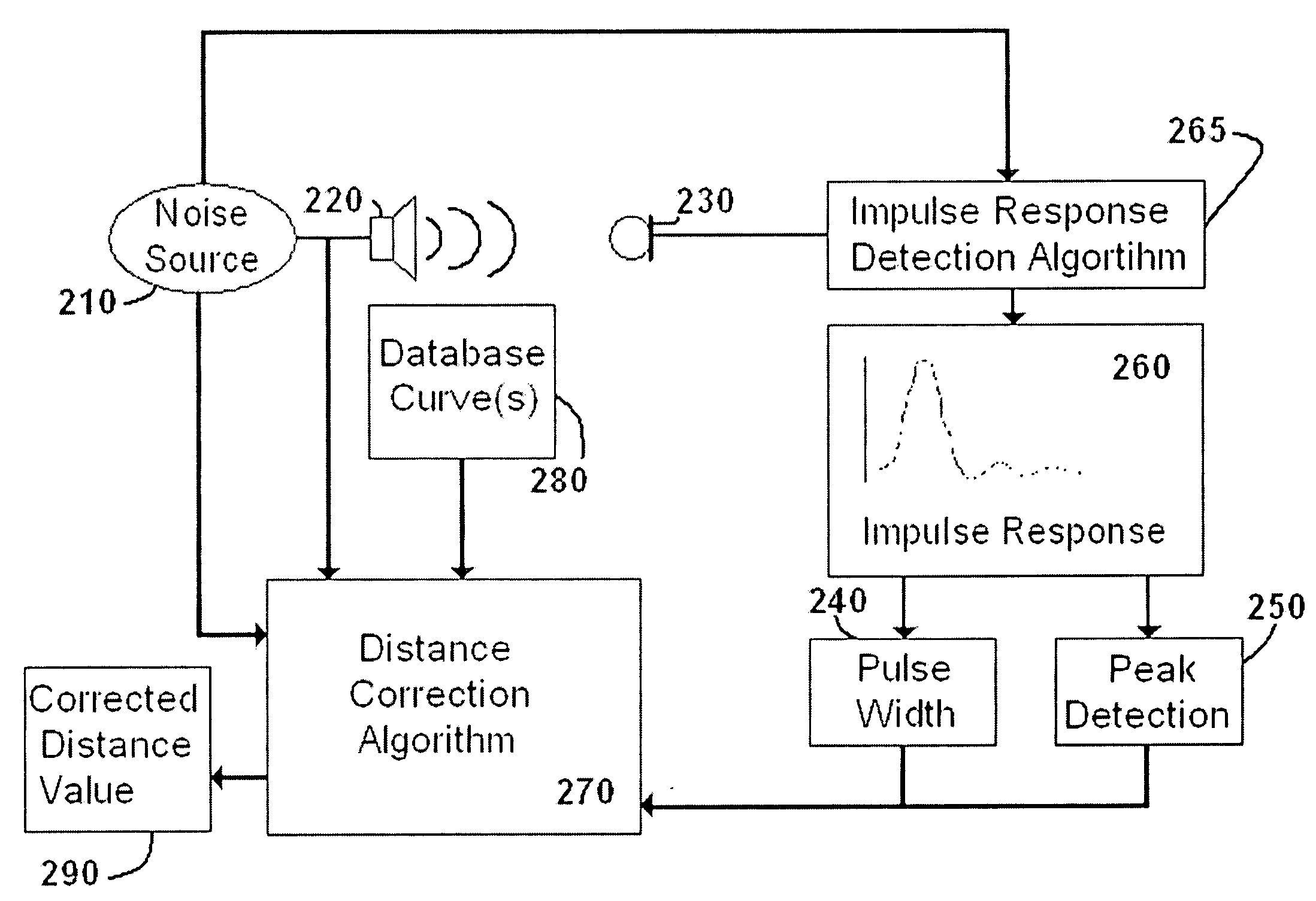
[0023]FIG. 3 is a block diagram of the apparatus of the present invention. For the sake of simplicity, many of the basic components in an auto-setup home theater system are not illustrated here for the sake of clarity. Referring to FIG. 3, a noise source 210 may be used to generate a sound pattern or series of impulses or the like through speaker 220. The actual sound used may encompass any of the known sound patterns known in the art for measuring speaker location and the like. Speaker 220 represents the system subwoofer or other speaker, which may be measured for the present test and calibration cycle.

[0024] Microphone 230 may be located by the consumer at a preferred listening location (e.g., near the head of the consumer at a favorite chair or the like). Microphone 230 picks up noise or other sound from speaker 220, which will be delayed by an amount of time equal to the speed of sound divided by the distance between microphone 230 and speaker 220. Other internal delays may, of...


PUM


Abstract

The present invention automatically corrects for subwoofer or other speaker crossover settings or other parameters by providing an adjustable factor passed upon not only pulse location, but on pulse width. In FIG. 2, as the low-pass frequency of the subwoofer is decreased, either by the crossover setting or the physical design of the subwoofer, the impulse response is shifted to the right and the width of the impulse increases. By relating the adjustment factor to the width of the impulse, the accuracy of the computed distance is greatly increased. The relation may be found doing a simple polynomial curve fitting to empirical data from several subwoofers at various crossover settings and distances, storing that data, and then measuring pulse location and width of the actual subwoofer during the setup routine, and adjusting the distance (delay) calculations accordingly.

Description

CROSS-REFERENCE TO RELATED APPLICATIONS [0001] The present application claims priority from Provisional U.S. Patent Application No. 60 / 612,474 filed on Sep. 23, 2004 (Cirrus Logic Docket No. 1537-DSP), and incorporated herein by reference.FIELD OF THE INVENTION [0002] The present invention relates to a method and apparatus for calibrating a home theater system. In particular, the present invention is directed toward a technique for measuring the distance between a subwoofer or other speaker and a listener location. BACKGROUND OF THE INVENTION [0003] Home theater systems provide a number of components, which may be located in various parts of the room. The components include the home theater receiver / amplifier, front stereo speakers (left and right), rear surround sound speakers (left and right), a center speaker, and a subwoofer. Various other combinations of speakers may also be used, including additional or fewer speakers. [0004] One problem with such systems is that a major aspec...

Claims


Application Information

Patent Timeline
Patent Type & Authority Applications(United States)
IPC IPC(8): H04R29/00G01C25/00G06F19/00
CPCH04S7/301G01S11/14
Inventor COOPER, JOEL C. MCKEE
Owner CIRRUS LOGIC INC
Why Eureka
Try Eureka