Motor

a motor and motor body technology, applied in the field of motors, can solve the problems of low cost, inability to achieve sufficient exact positioning of hall-effect sensors, and no motor in which such secondary measures have been implemented, and achieve the effect of improving motor reliability and facilitating and accurately determining

Inactive Publication Date: 2006-03-23
NIPPON DENSAN CORP
View PDF39 Cites 45 Cited by
  • Summary
  • Abstract
  • Description
  • Claims
  • Application Information

AI Technical Summary

Benefits of technology

[0007] The present invention in electrically powered motors enables the positions of the armature core and the sensor-mounting member relative to each other to be easily and accurately determined. In addition, by restricting movement of an electrical component in the unlikely event that the component should come out of its fixed position, the invention contributes to improving motor reliability.

Problems solved by technology

Nevertheless, in motors to date, low-cost, sufficiently exact locating of the Hall-effect sensors has not been achieved.
With motors to date, however, no motor in which such secondary measures have been implemented has existed.

Method used


Image

  • Motor
  • Motor
  • Motor

Examples


Embodiment Construction

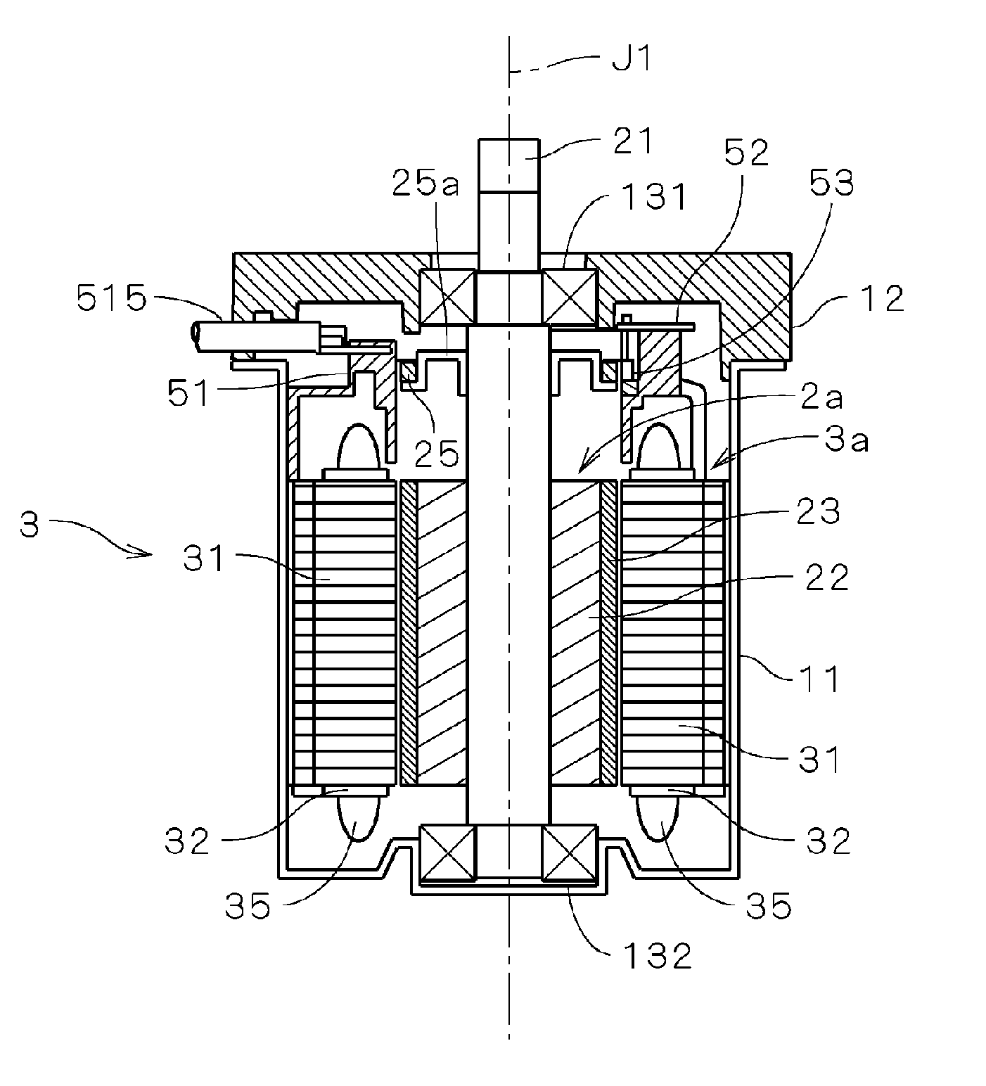
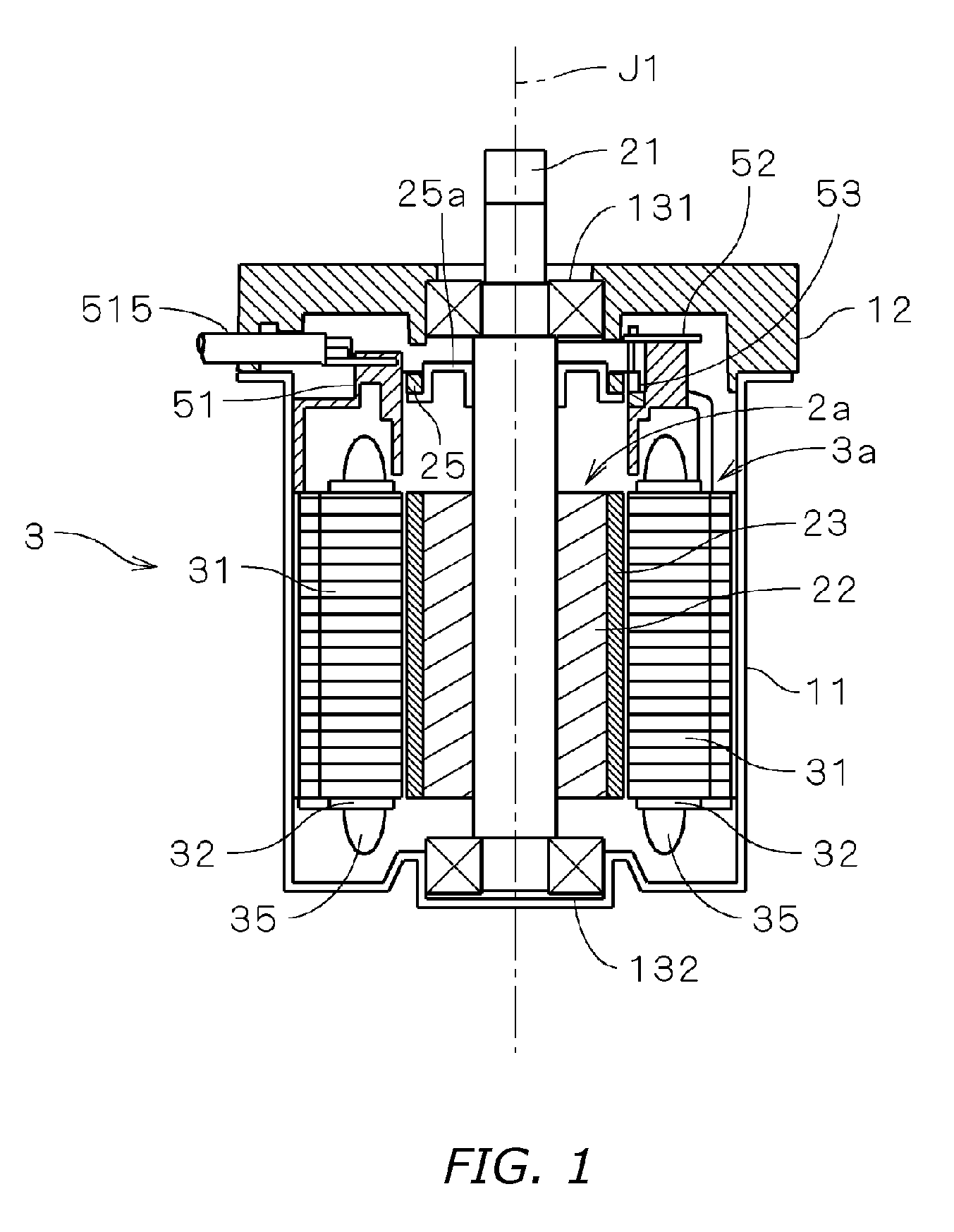
[0025] Reference is made to FIG. 1, a vertical section view of an electrically powered motor 1 involving one embodiment of the present invention. The motor 1 is a so-called brushless motor, and is employed, for example, as a drive source that assists steering operations in an automobile power-steering system. (It should be noted that the shading by parallel diagonal lines has been omitted from the sectional illustration of the finer features in FIG. 1.) The motor 1 is covered by a cylindrical housing 11 that is open along the upper end in FIG. 1, and by a cover part 12 that closes over the opening in the housing 11, and in the center of which an opening is formed. Further, ball bearings 131 and 132 are respectively mounted in the opening in the cover part 12, and in the base of the cylindrical housing 11. The motor shaft 21 is rotatably supported by the ball bearings 131 and 132.

[0026] A columnar rotor yoke 22 in the housing 111 interior is attached to the shaft 21. In turn, a fiel...


PUM


Abstract

A motor stator section (3a) is furnished with a busbar (51) attached to an armature (3), and with a circuit board (52) attached to the busbar (51). A parts accommodation recess (516) is formed in the busbar (51) surface that opposes the circuit board (52), and a holding recess (512), in which is anchored a sensor holder (54) that retains Hall sensors (53) mounted on the circuit board (52) is formed in the busbar (51) inner circumferential surface. Further, grooves are formed in the circuit board (52), the sensor holder (54), and the busbar (51), wherein fitting a jig (9) to these grooves enables high-precision assembly of these components.

Description

BACKGROUND OF THE INVENTION [0001] 1. Technical Field [0002] The present invention relates to electrically powered motors that are installed in vehicles. [0003] 2. Description of the Related Art [0004] As a device for assisting automotive vehicle driving operations, hydraulic power steering, with which the operation of the steering wheel is assisted by means of hydraulic pressure generated by a pump run by engine output power, has traditionally been employed. In recent years, meanwhile, electric power assisted steering (abbreviated “EPAS” hereinafter), with which steering wheel operation is assisted by a motor rotationally powered by a vehicle on-board battery, has come into use. This latter power steering system, whereby engine power loss is low compared to systems that use the engine's rotation to generate hydraulic pressure, is receiving attention for its efficiency. In the motors employed in such EPAS systems, a diverse variety of electronic components that serve to realize high...

Claims


Application Information

Patent Timeline
Patent Type & Authority Applications(United States)
IPC IPC(8): H05K1/00H01R12/00
CPCH02K3/522H02K2203/09H02K29/08H02K5/225
Inventor KATAOKA, NAKABAMIGITA, TAKAYUKISUZUKI, HIROAKI
Owner NIPPON DENSAN CORP
Why Eureka
Try Eureka