Method of manufacturing a golf club head with a variable thickness face

a golf club and variable thickness technology, applied in the field of golf club head manufacturing, can solve the problems of face that is prone to fatigue cracks, cannot be properly machined on a lathe, and the formation of an elliptical reinforced region presents special problems, so as to achieve the effect of varying the thickness of the face inser

Active Publication Date: 2006-03-23
KARSTEN MFG CORP
View PDF15 Cites 22 Cited by
  • Summary
  • Abstract
  • Description
  • Claims
  • Application Information

AI Technical Summary

Benefits of technology

[0006] The method for manufacturing a golf club face insert includes locating a ball end mill revolving about an axis generally normal to the inner surface of the face plate at an initial location on a first circumferential intersection between the outer edge of the central thickened region and the transition region. The inner surface of the face plate is machined by moving the revolving ball end mill in a radial direction outwardly toward and through the transition region and the peripheral region to machine the inner surface of the face plate creating a tool channel having a width as the ball end mill traverses the transition region and the peripheral region and thereby vary the thickness of the face insert in the tool channel. The ball end mill is then raised in a direction normal to the surface of the face plate and relocated to a subsequent location on the first circumferential intersection adjacent to the previous tool channel. The steps of machining, raising and relocating the ball end mill are repeated until the end mill has traversed the entire circumference of the circumferential intersection. In preferred embodiments, the machining step may vary the thickness of the transition region from the first thickness to a second thickness. The ball end mill may traverse the transition region along a variable path, which may be a straight line, a curved line, or any other suitable path.

Problems solved by technology

For clubs in which the club face is machined from a wrought alloy sheet or other sheet material, forming an elliptical reinforced region presents special problems.
The face cannot be machined properly on a lathe because the lathe will produce only a circular reinforced region.
In addition, removing portions of the club face using a cutter in an elliptical pattern may result in a face that is prone to fatigue cracks.

Method used


Image

  • Method of manufacturing a golf club head with a variable thickness face
  • Method of manufacturing a golf club head with a variable thickness face
  • Method of manufacturing a golf club head with a variable thickness face

Examples


Embodiment Construction

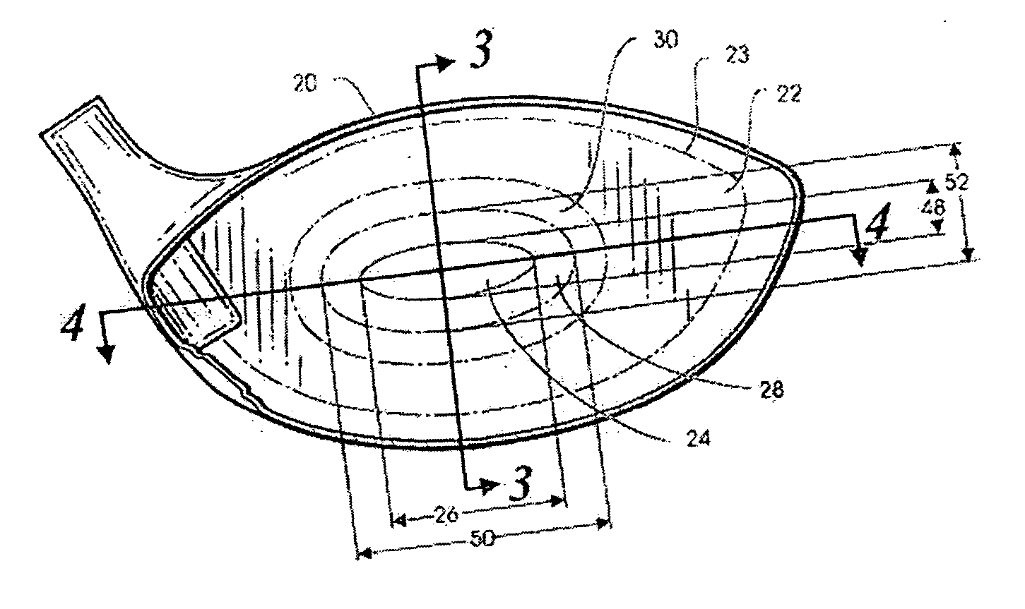
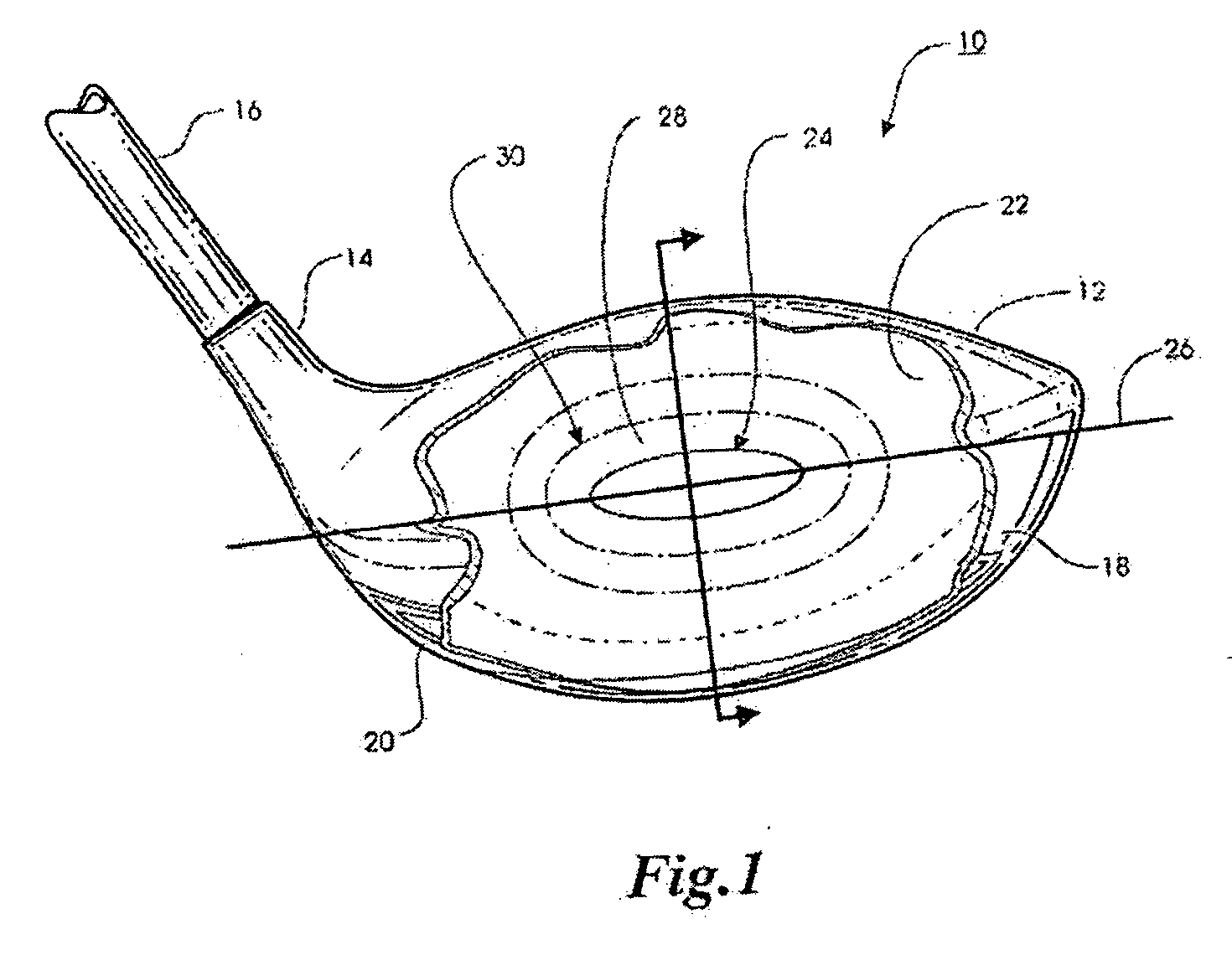
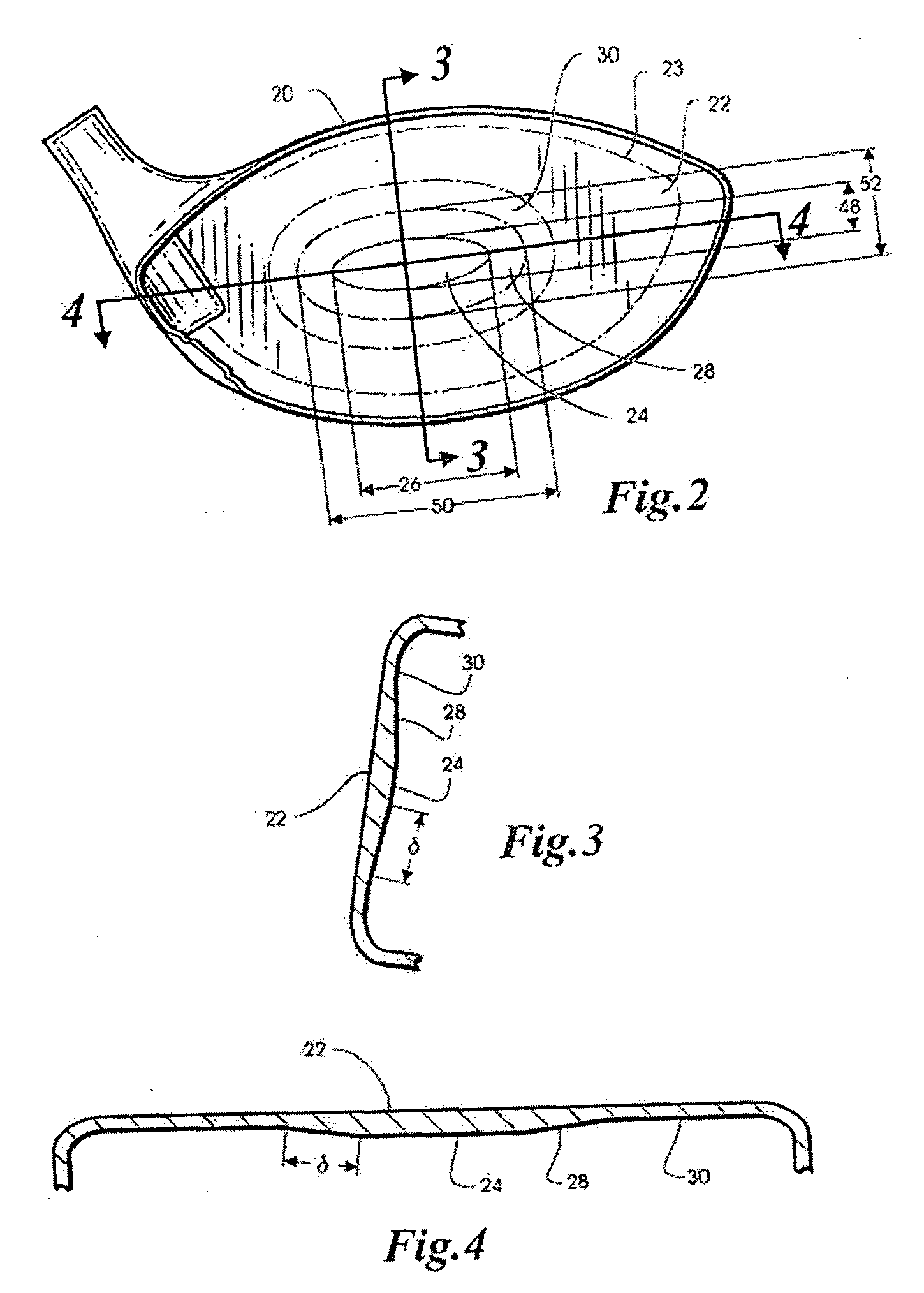
[0014] Referring to FIG. 1, a golf club 10 includes a head 12, a hosel 14 and a shaft 16. Head 12 includes a hollow body 18 made of a metal material such as titanium. Hollow body 18 is formed as a shell 20, which may be assembled from a series of forged pieces but, in the illustrative embodiment, comprises a titanium investment casting. A face plate 22 is attached by conventional means such as plasma or electron beam welding to a corresponding opening 23 (FIG. 2) in shell 20 to form hollow body 18. Face plate 22 may be a conventional forged blank but, in the illustrative embodiment, comprises a rolled sheet titanium blank that is machined prior to welding to shell 20 as described more fully hereinafter.

[0015] As noted hereinbefore, because a golfer's swing tends to vary more in the heel-toe direction than it does up or down, the inventor of the present invention determined that the most efficient reinforcement would be a thickened region that is preferably elliptical and oriented s...


PUM

PropertyMeasurementUnit
aspect ratioaaaaaaaaaa
distanceaaaaaaaaaa

Abstract

A method of manufacturing a golf club head with a variable thickness face having a central thickened region surrounded by a transition region tapering from the central thickened region to a thinner peripheral region. The method includes locating a ball end mill revolving about an axis generally normal to the inner surface of the face plate at an initial location on a circumferential intersection between the outer edge of the central thickened region and a transition region. The inner surface of the face plate is machined by moving the revolving ball end mill in a radial direction outwardly toward and through the transition region and the peripheral region to machine the inner surface of the face plate creating a tool channel having a width as the ball end mill traverses the transition region and thereby vary the thickness of the face plate in the tool path. The ball end mill is then raised in a direction normal to the surface of the face plate and relocated to a subsequent location on the circumferential intersection adjacent to the previous tool channel. The steps of machining, raising and relocating the ball end mill are repeated until the end mill has traversed the entire circumference of the circumferential intersection. In preferred embodiments, the machining step may vary the thickness of the transition region along a variable path, which may be a straight line, a curved line, or any other suitable path.

Description

CROSS REFERENCE TO RELATED APPLICATION [0001] This is a continuation-in-part of application Ser. No. 10 / 803,837, filed Mar. 17, 2004, and incorporated herein by reference.BACKGROUND OF THE INVENTION [0002] This invention relates generally to golf equipment and, in particular, to a golf club head with a variable thickness face and a method of manufacturing the same. [0003] Recent developments in golf club design have included improvements in drivers, which are clubs used primarily to strike a golf ball resting on a golf tee. These improvements have resulted in drivers with club heads consisting of a hollow shell usually made of metal, such as steel, aluminum, or titanium. These hollow shells have relatively thin walls including a thin front wall that is used to impact the golf ball. In order to prevent the front wall of these hollow shells from permanently deforming or cracking upon ball impact, it has become necessary to reinforce the front wall. One example of a golf club head cons...

Claims


Application Information

Patent Timeline
Patent Type & Authority Applications(United States)
IPC IPC(8): A63B53/04B21K17/00
CPCA63B53/0466A63B2053/0408A63B2053/0416A63B2053/0458B23C3/16Y10T29/4998B23C2220/48A63B2053/042A63B2053/0462Y10T29/49995B23C5/1009A63B60/00A63B53/0408A63B53/0416A63B53/042A63B53/0458A63B53/0462B23C3/00
Inventor SCHWEIGERT, BRADLEY D.SOLHEIM, JOHN A.
Owner KARSTEN MFG CORP
Why Eureka
Try Eureka