Probe guide for use with medical imaging systems

a technology for medical imaging and guide, applied in the field of guide, can solve the problems of limited to the geometry of the imaging device, and the targeted area is limited to the design of the imaging devi

Inactive Publication Date: 2006-03-23
MEDICAL EQUIP DIVERSIFIED SERVICES
View PDF21 Cites 66 Cited by
  • Summary
  • Abstract
  • Description
  • Claims
  • Application Information

AI Technical Summary

Benefits of technology

[0006] According to an embodiment of the invention, an improved probe guide for use in conjunction with a medical imaging device is disclosed. The medical imaging device may be any type of imaging device that generates a cross-sectional image of a portion of a patient's body in a single image plane, such as, ultrasound, CT, or MRI imaging devices. The probe guide of the invention allows accurate placement of a probe, such as a biopsy needle, by allowing a range of angular translation of the probe.
[0009] A first encoder is incorporated into the hinge and the first encoder is used for detecting angular orientation of the imaging device holder relative to the probe guide body. The probe holder has a second encoder incorporated therein for detecting angular orientation of the probe relative to the probe guide body and the linear position of the probe within the probe guide body. This effectively provides information about the position of the probe relative to the image plane. The probe holder of this embodiment of the invention allows accurate placement of a probe, such as a biopsy needle, by allowing a range of both angular and lateral translation of the probe. The angular orientation and the lateral position of the probe is used to extrapolate or project the probe's penetration path and superimpose the penetration path on to the cross-sectional image formed by the medical imaging device to guide the physician.
[0013] A benefit of the probe guide of the invention is that it allows accurate placement of a probe, such as a biopsy needle, by allowing a range of angular translation as well as axial translation of the probe.

Problems solved by technology

Such fixed plane biopsy guide was generally rigidly attached to the imaging device and was limited to the geometry of the imaging device.
The targeted areas were limited to the design of the imaging device.

Method used


Image

  • Probe guide for use with medical imaging systems
  • Probe guide for use with medical imaging systems
  • Probe guide for use with medical imaging systems

Examples


Embodiment Construction

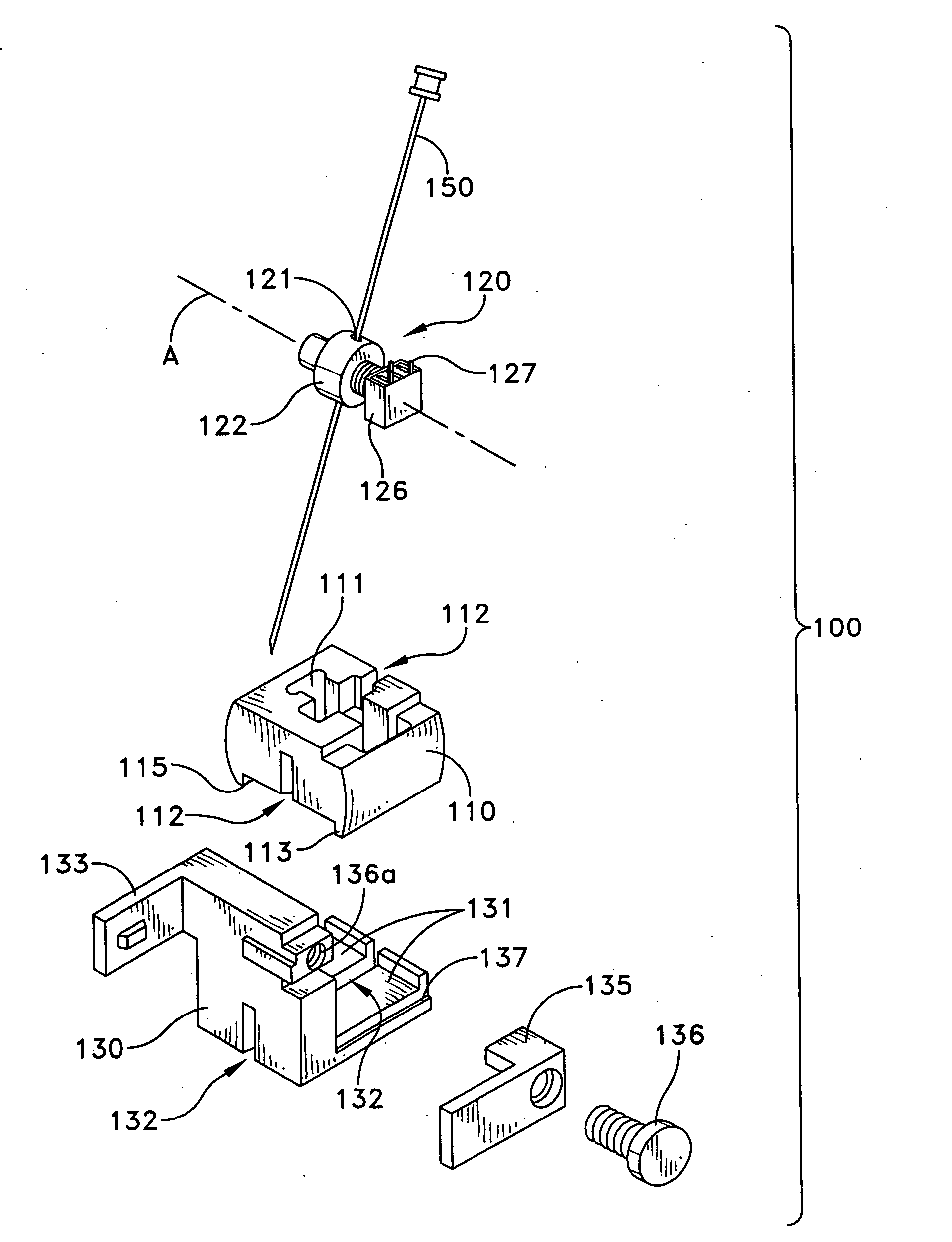
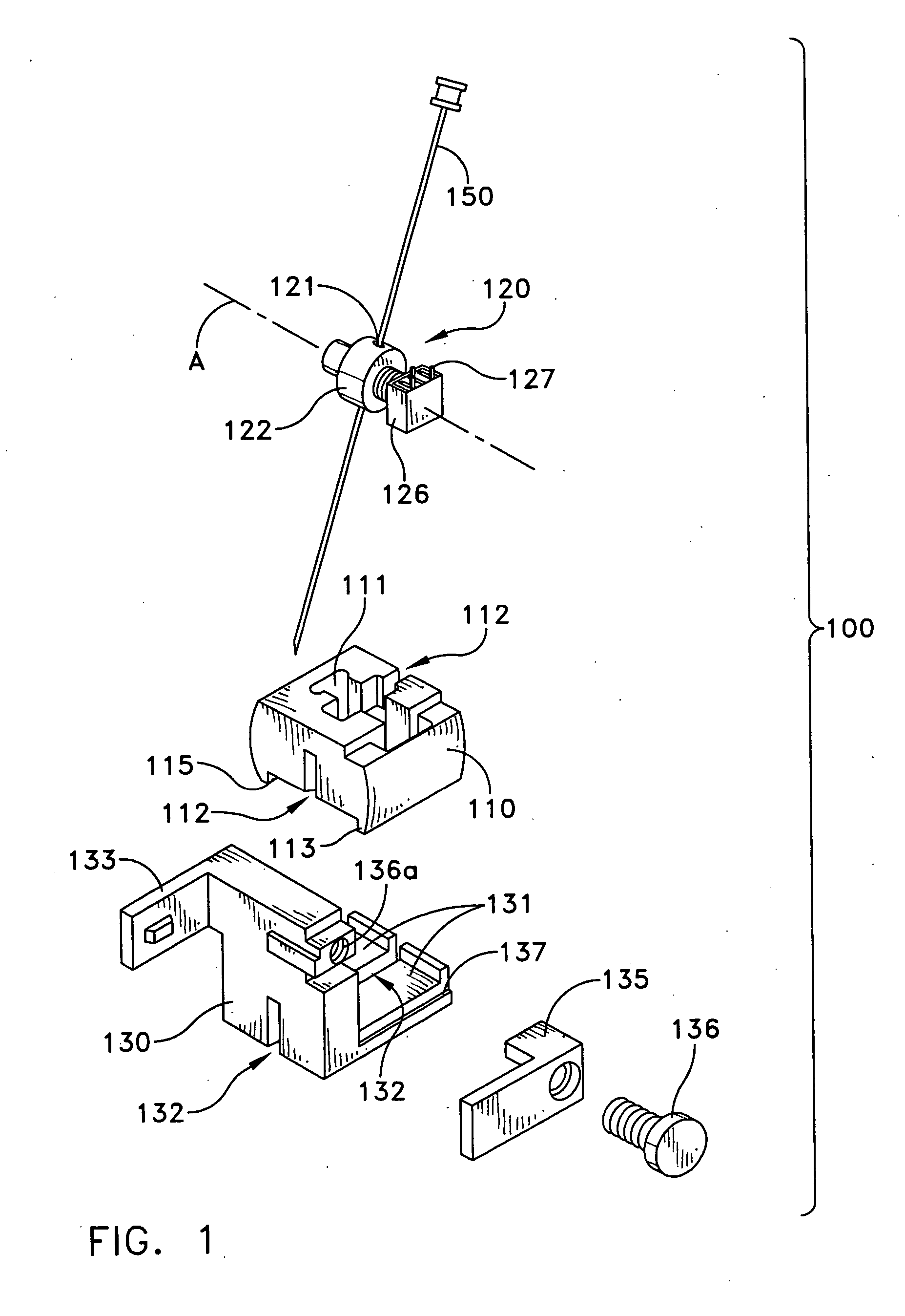
[0044] Referring to FIGS. 1-1F, disclosed herein is a probe guide 100 for use in conjunction with a medical imaging device 190, according to an embodiment of the invention. The medical imaging device 190 illustrated in this example is an ultrasound transducer but the various embodiments of the probe guide may be used in conjunction with any type of imaging device that generates a cross-sectional image of a portion of a patient's body in a single image plane, such as, ultrasound, CT, or MRI imaging devices.

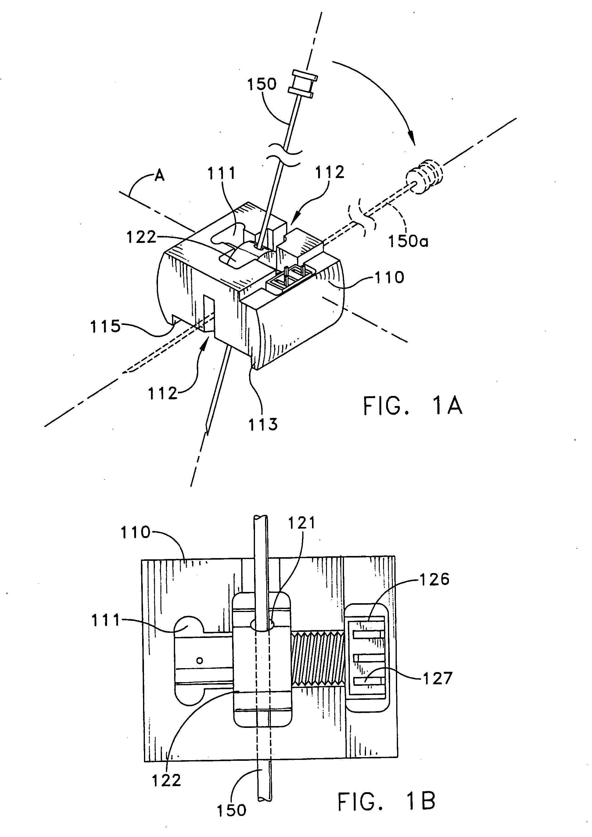
[0045]FIG. 1 is an exploded view of the probe guide 100. The probe guide 100 may comprise a probe guide body 110 having a connecting mechanism 130 for connecting the probe guide 100 to the medical imaging device 190 (shown in FIGS. 1E and 1F). A probe holder 120 for holding a probe 150 is provided in the probe guide body 110. The probe guide body 110 has a cavity 111 for receiving the probe holder 120. FIG. 1A illustrates an assembled probe guide body 110 with the probe holder 120...


PUM


Abstract

An improved probe guide and probe guide system for use in conjunction with a medical imaging device is disclosed. The medical imaging device may be any type of imaging device that generates a cross-sectional image of a portion of a patient's body in a single image plane, such as, ultrasound, CT, or MRI imaging devices. The probe guide allows maintaining the movement of the probe within the image plane and accurate placement of a probe, such as a biopsy needle, by allowing a range of angular translation of the probe. The probe guide system enables extrapolation of the penetration path of the probe held by the probe guide and superimpose it on to the cross-sectional image allowing the medical personnel to view the penetration path of the probe within the patient in advance.

Description

CROSS-REFERENCE TO RELATED APPLICATIONS [0001] This application claims the benefit of U.S. Provisional patent application Ser. No. 60 / 611,123, filed on Sep. 17, 2004, which is incorporated herein by reference.FIELD OF THE INVENTION [0002] The invention relates to a probe guide that can be utilized with different modes and models of single plane medical imaging devices, such as, ultrasound, computer aided tomography (CT), and magnetic resonance imaging (MRI). BACKGROUND OF THE INVENTION [0003] It is well known in the medical industry that single plane imaging systems are useful for performing the localizing of specific tissues for procedures such as biopsies, and the destruction of diseased tissues using various clinical techniques such as heat, cold, and chemical applications. In such procedures, the placement of therapeutic probes, guided by imaging devices, are used. Advantageously, the needle or probe is visible during the surgical procedure. [0004] In the past, a biopsy or thera...

Claims


Application Information

Patent Timeline
Patent Type & Authority Applications(United States)
IPC IPC(8): A61B6/00
CPCA61B17/3403A61B2019/467A61B2017/3413A61B19/5225A61B8/4209A61B90/37A61B2090/067
Inventor CANNON, CHARLES JR.HULL, DAVIDCAMERER, WILLIAM R. III
Owner MEDICAL EQUIP DIVERSIFIED SERVICES
Why Eureka
Try Eureka