Differential GPS corrections using virtual stations

a virtual station and gps technology, applied in wave based measurement systems, navigation instruments, instruments, etc., can solve the problems of increasing the total location error of a dgps calculation to tens of meters or larger, and the differential gps corrections for location and/or time determination are usually limited, so as to reduce the size

Inactive Publication Date: 2006-03-23
TRIMBLE NAVIGATION LTD
View PDF72 Cites 47 Cited by
  • Summary
  • Abstract
  • Description
  • Claims
  • Application Information

AI Technical Summary

Benefits of technology

[0043] The invention meets this need by providing three or more fixed Global Positioning System (GPS) signal antennas and associated receiver/processors, referred to as GPS reference stations, with known locations, that receive and analyze GPS signals from each of three or more GPS satellites, using certain approximations to extend the pseudorange and/or pseudorange rate corrections to a much larger region S. The GPS may be replaced by a Global Orbiting Navigational Satellite System (GLONASS) or any similar satellite-based Satellite Positioning System (SATPS) for location determination; these are discussed in detail below. These GPS reference stations may be positioned at or near the boundary of S and/or may be positioned throughout the interior of S as well. Each reference station determines the pseudorange corrections for GPS at its location and transmits this information as one or more packets in RTCM SC-104 format to a central station. Alternatively, the reference station does at most part of the signal processing and transmits the partly processed or unprocessed pseudorange, pseudorange rate and/or carrier phase information in packets to the central station for subsequent signal processing. Each packet from a reference station includes a station id. and includes a parameter indicating the present status of that reference station. This may include RTCM messages of types 1, 2, 3, 5, 6, 7, 9, 16 and/or proprietary formats that are part of new message type 59.
[0044] The central station concatenates the packets into a binary stream that is fed to a Trimble Net 4000 or equivalent GPS signal processor to det

Problems solved by technology

However, differential GPS (DOPS) corrections for determinations of location and/or time are usually limited to a region no more than a few hundred kilometers (kin) in diameter.
For regions of larger diameter, error

Method used


Image

  • Differential GPS corrections using virtual stations
  • Differential GPS corrections using virtual stations
  • Differential GPS corrections using virtual stations

Examples


Embodiment Construction

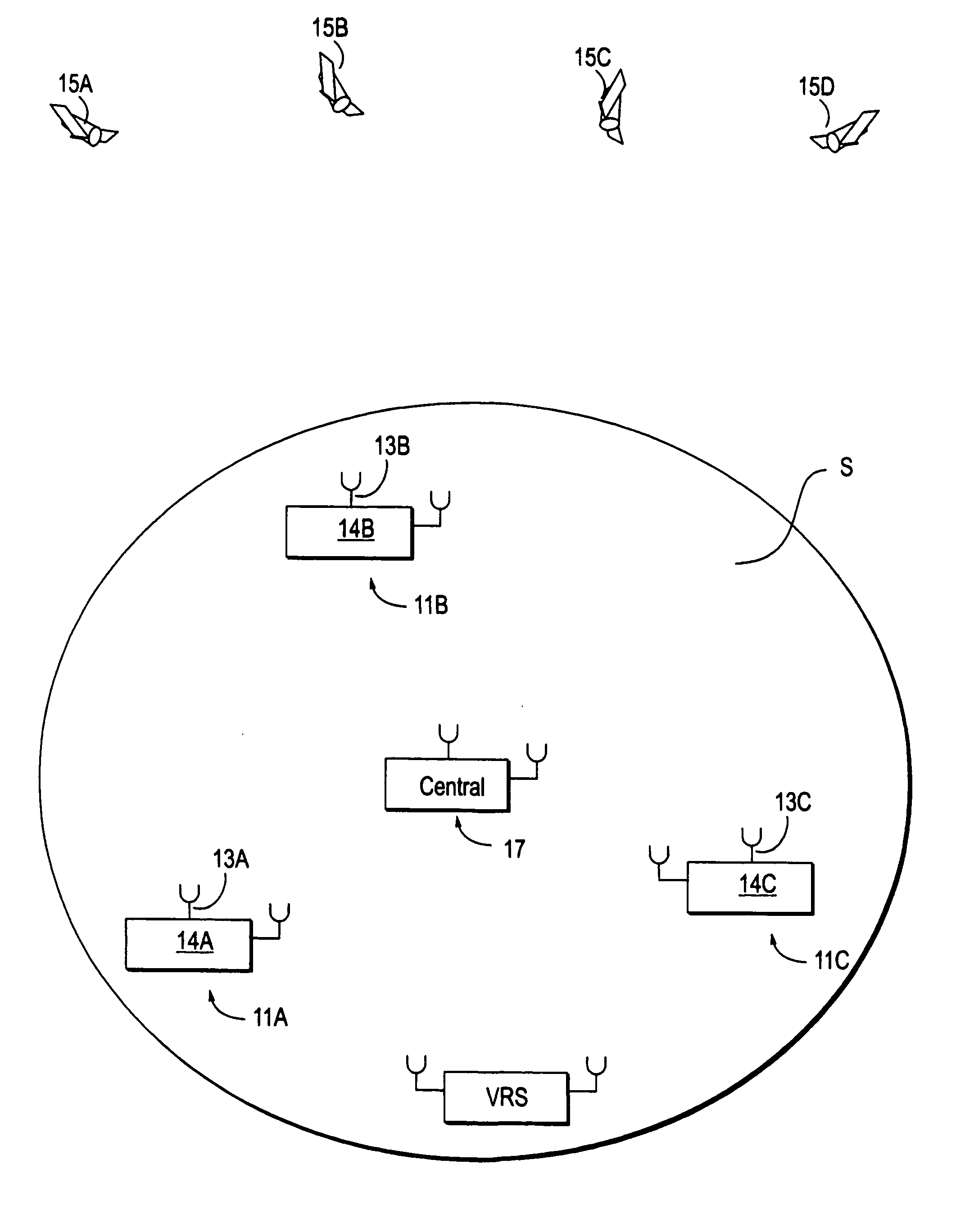
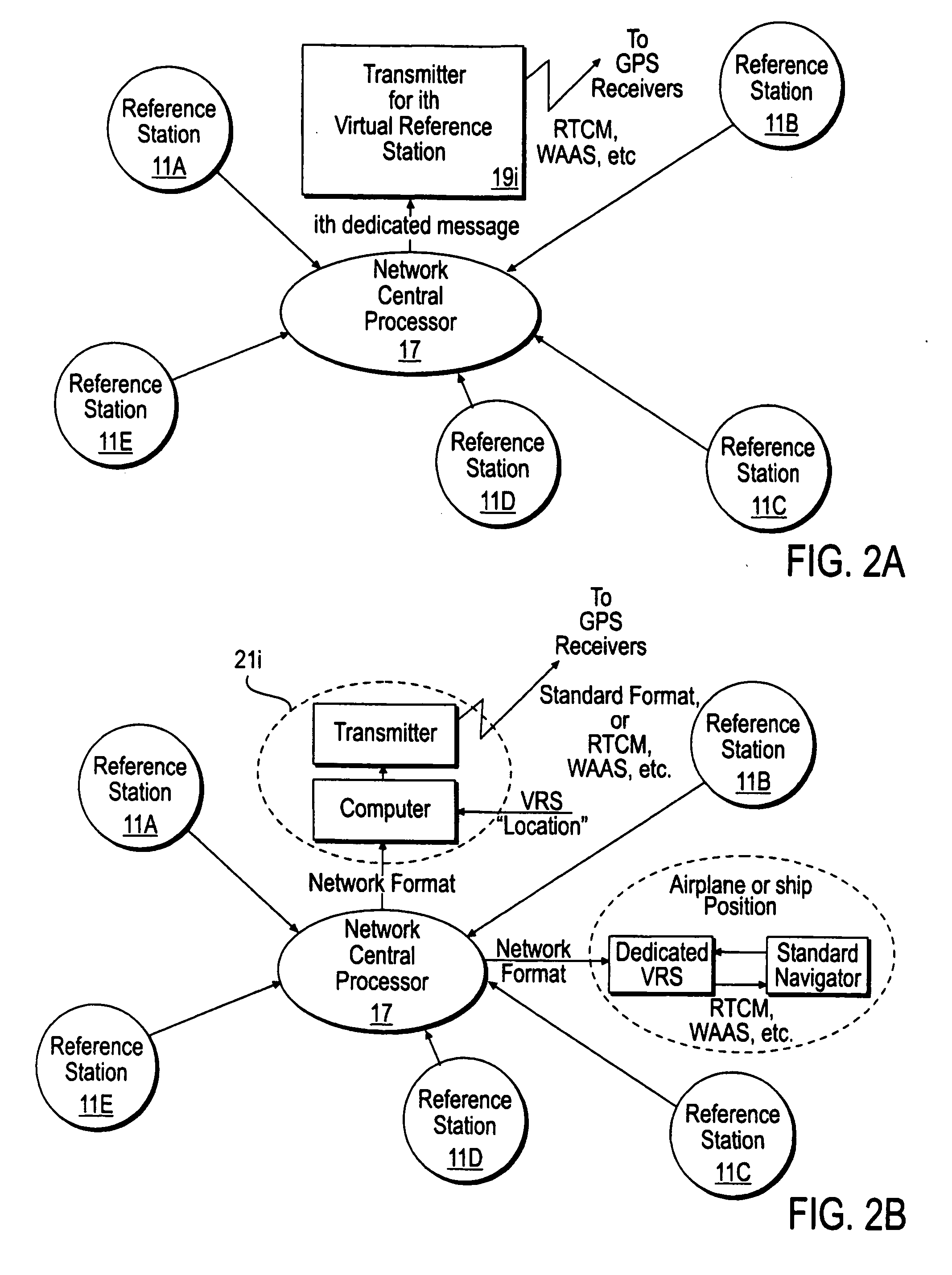
[0049]FIG. 1 illustrates use of the invention to cover a large region S, which may extend over the entire Earth or may have a smaller diameter. Each of three or more GPS reference stations 11A, 11B, 11C, with GPS signal antennas 13A, 13B, 13C, and receiver / processors 14A, 14B, 14C receives GPS signals, including pseudorange information, from several common-view GPS satellites 15A, 15B, 15C, 15D. A common-view” satellite is visible from the sites of at least three reference stations at the same observation times. The location coordinates of each of the reference stations 11A, etc. is known with high accuracy, either by use of a surveyor by some other means. As each reference station 11A, 11B, 11C, receives the GPS signals from each of the GPS satellites 15A, 15B, 15C, the GPS-determined pseudorange for the GPS antenna for that station and that satellite is compared with a calculated pseudorange for that station and that satellite, and GPS pseudorange corrections PRC(t;t0;m;n) are gen...


PUM


Abstract

Method and apparatus for providing GPS pseudorange correction and carrier phase correction information for navigation or surveying activities over a selected geographic region S of arbitrary size. In a navigation mode, a virtual reference station (VRS), positioned near a selected location L, receives differential GPS (DGPS) correction signals, translates these signals into a selected format, and broadcasts this DGPS information in this format for use by a local user. In a survey mode, the VRS receives corrected GPS information, translates this information into a selected format and broadcasts this translated and corrected GPS information and the VRS location, for use by a mobile station in forming a baseline vector from the GPS mobile station to the VRS location.

Description

FIELD OF THE INVENTION [0001] This patent application is a continuation of application, U.S. Ser. No. 09 / 019,495, filed on 5 Feb. 1998, which is a continuation of application, U.S. Ser. No. 08 / 414,444, filed on 31 Mar. 1995, which is a continuation in part of application, U.S. Ser. No. 08 / 177,012, filed on 3 Jan. 1994 and-assigned to the Assignee of this application. This-invention relates to a network of Global Positioning System stations for providing code phase or carrier phase differential corrections to enhance the accuracy of location information over a wide area.BACKGROUND OF THE INVENTION [0002] Differential corrections for location information provided by a Global Positioning System (GPS) offer the possibility of reducing the inaccuracies in location and observation time provided by such system from tens of meters to one meter or less and tens of nanoseconds or less, respectively. However, differential GPS (DOPS) corrections for determinations of location and / or time are us...

Claims


Application Information

Patent Timeline
IPC IPC(8): G01C21/28G01C21/36G01S19/25G01S5/14G01S19/07G01S19/41G01S19/43
CPCG01C15/00G01C21/28G01S19/43G01S19/258G01S19/41G01S19/07G01S19/071
Inventor ROBBINS, JAMES E.
Owner TRIMBLE NAVIGATION LTD
Why Eureka
Try Eureka