Routed layout optimization with geotopological layout encoding for integrated circuit designs

a geotopological layout and integrated circuit technology, applied in the field of integrated circuit designs and postlayout optimization, can solve the problems of product lateness, loss of revenue and market share, and difficulty for ic designers and engineers, and achieve the effect of being easily modifiabl

Inactive Publication Date: 2006-03-23
NANNOR TECH
View PDF12 Cites 8 Cited by
  • Summary
  • Abstract
  • Description
  • Claims
  • Application Information

AI Technical Summary

Benefits of technology

[0018] With the geotopological layout encoding graph, a routed layout is readily modifiable for various optimization targets, while advantageously maintaining the exact routing path(s) of unmodifiable nets.

Problems solved by technology

Because products that are late to the market are likely to lose revenue and market share, as the product life cycles become shorter and shorter, the design time also becomes very important.
Consequently, achieving a specified chip performance, which continues to increase, within a designated design time frame, which seems to keep shrinking, present a constant challenge to IC designers and engineers alike.
Unfortunately, system-on-a-chip (SOC) complexities reaching into the tens of millions of gates have made gate-level design planning inadequate.
Without the structural information that is part of a gate-level design description, however, it is very difficult to estimate design parameters, such as on-chip timing delays, power dissipation, and chip size.
Indeed, because of the lack of precise geometry information of wires, design verification in stages before detail routing inevitably all must base on some predictions.
However, due to the high complexity and large scale of the designs, performing an optimization after detail routing (i.e., post-layout optimization) is very difficult and continues to be a challenge today.
In most cases, the local resource is inadequate for any layout change.
The difficulty in post-layout optimization and the fact that engineers generally like to make design decisions as early in the design process as possible explain the lack of viable post-layout optimization tools on the market, contrasting the number of various logical design and planning tools as well as physical placement and routing tools readily available today.
The downside is that a typical back-end design iteration usually takes days to process and compute.
This approach therefore places a heavy burden on the design time issue as mentioned before.
Another drawback is that, due to the indirect approach, the additional design iteration cannot guarantee those layout modifications.
Furthermore, verification error is almost unavoidable, which makes the subsequent optimization less effective and useful.

Method used


Image

  • Routed layout optimization with geotopological layout encoding for integrated circuit designs
  • Routed layout optimization with geotopological layout encoding for integrated circuit designs
  • Routed layout optimization with geotopological layout encoding for integrated circuit designs

Examples


Embodiment Construction

[0024] In the following detailed description, like numbers and characters may be used to refer to identical, corresponding, or similar items in different figures.

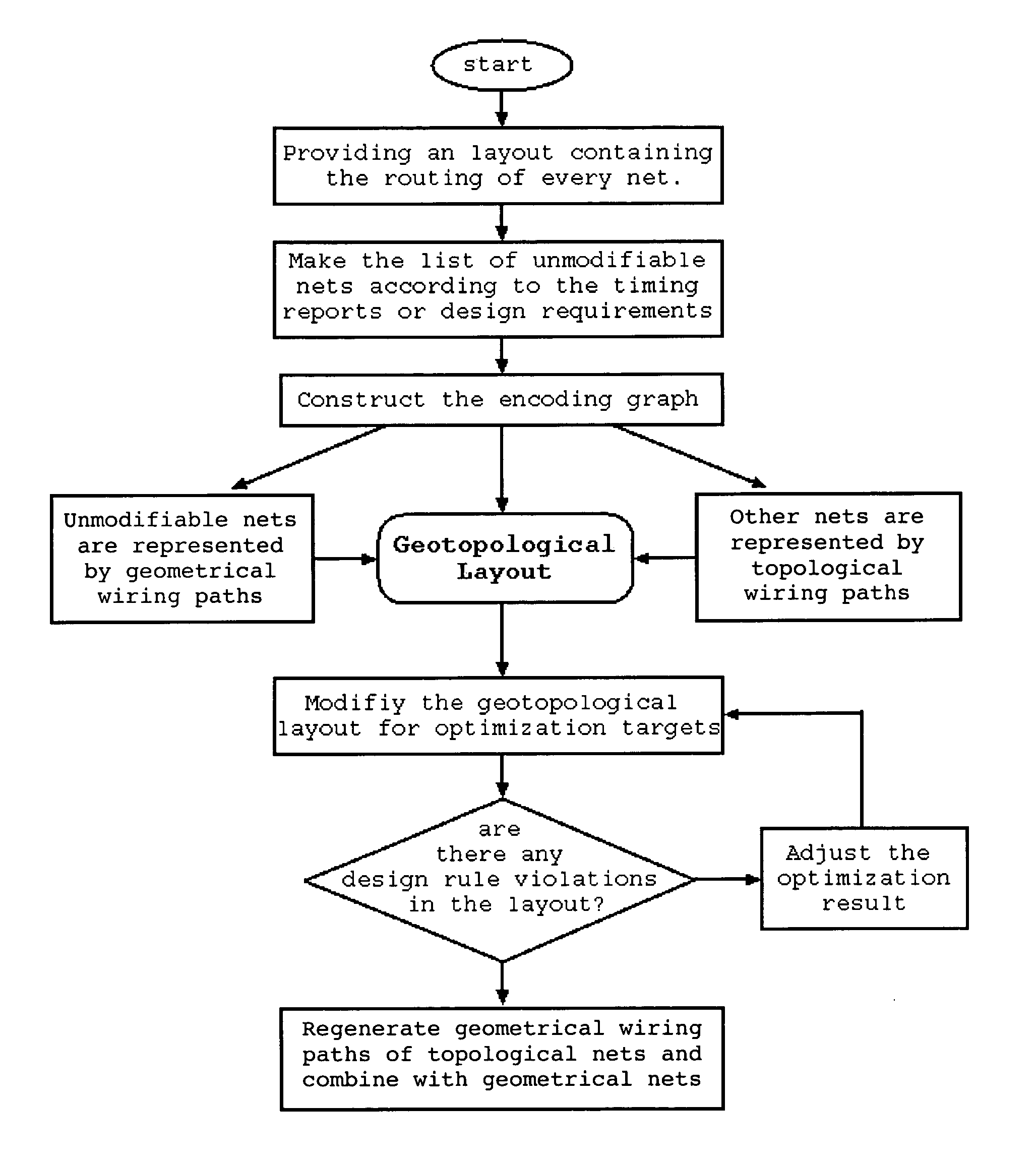
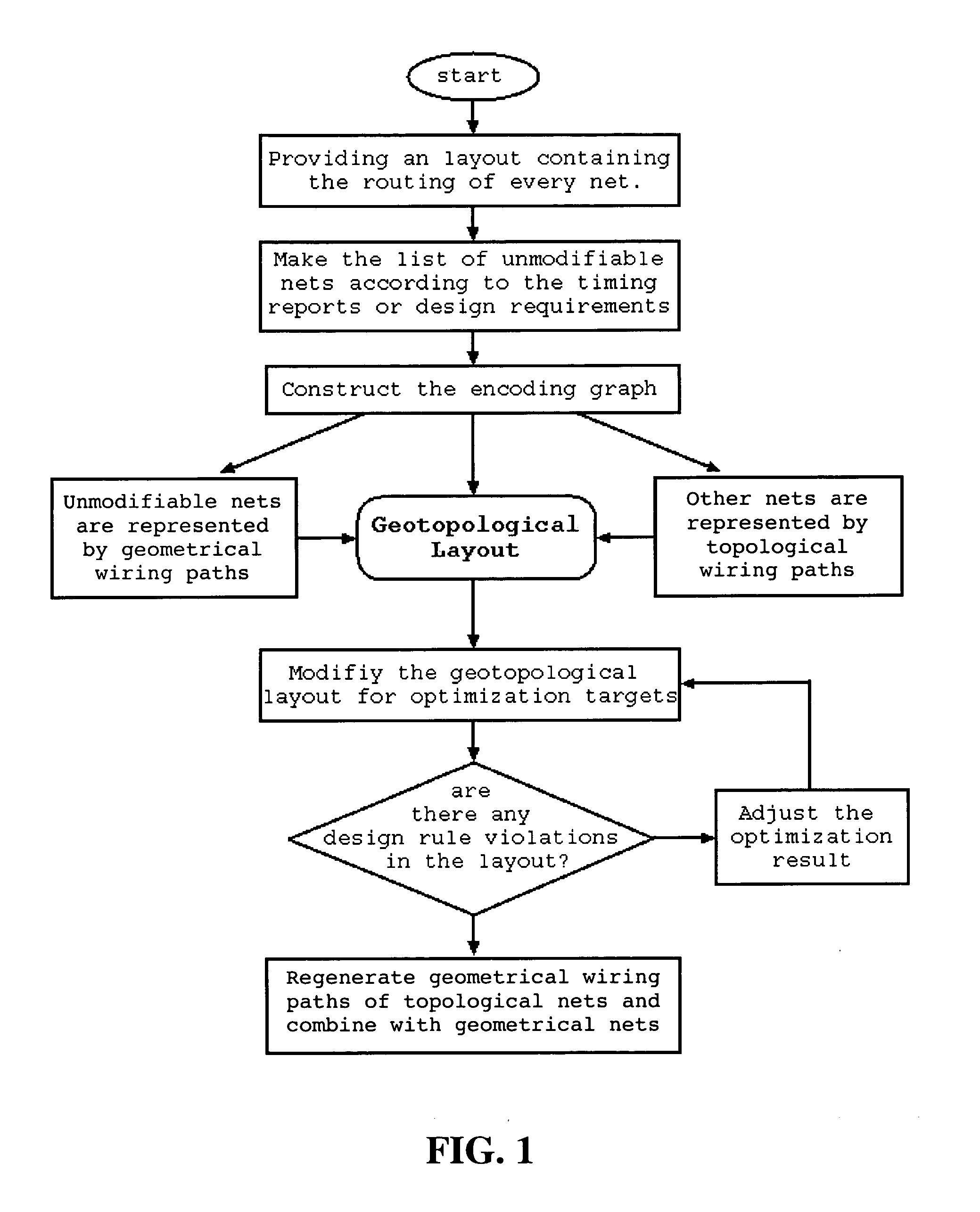
[0025] An effort has been made to modify the routed layout through the topological representation of the layout, or the topological layout, see, Zhang, S. and Dai, W. “TEG: A New Post-Layout Optimization Method,” IEEE Transactions on Computer-Aided Design of Integrated Circuits and Systems, Vol. 22, No. 4, April 2003, pp. 1-12, the content of which is incorporated herein by reference in its entirety, hereinafter referred to as the “topological approach”. Readers are directed to the article for further teachings on underlying operations such as layout updates, design rule check, wire representations, etc.

[0026] In the topological approach, a topological layout is extracted from the geometrical layout. Specified layout modifications, such as wiring sizing and spacing or rip-up and reroute, are then performed on the topologi...


PUM


Abstract

The present invention provides a new way of optimizing integrated circuit (IC) designs in the physical design stage after detail routing. A key element is a novel hybrid layout representation referred to as the geotopological layout in which some nets are represented by their determined geometrical wiring paths and some by their respective wiring topology at the same time. In the IC design flow, a routed layout with geometrical wiring paths is transformed into a geotopological layout. All layout modifications are then performed according to the geotopological layout. An embedded design rule checker ensures the validity thereof. Finally, a new geometrical layout is regenerated accordingly, including all the layout changes for the targeted optimization. This geotopological approach advantageously enables an IC designer to modify a routed layout for various optimization targets, while advantageously maintaining the exact routing paths of critical nets that are not modifiable.

Description

CROSS-REFERENCE TO RELATED APPLICATIONS [0001] This application relates to a co-pending U.S. patent application Ser. No. ______, which is filed concurrently herewith and entitled, “AUTOMATIC LAYOUT YIELD IMPROVEMENT TOOL FOR REPLACING VIAS WITH REDUNDANT VIAS THROUGH NOVEL GEOTOPOLOGICAL LAYOUT IN POST-LAYOUT OPTIMIZATION,” and which is incorporated herein by reference in its entirety.BACKGROUND OF THE INVENTION [0002] 1. Field of the Invention [0003] This invention relates generally to integrated circuit designs and post-layout optimization therefor. More particularly, it relates to a new physical design optimization flow system and method embodying a novel geotopological layout representation to modify the routed layout useful for a variety of optimization purposes. [0004] 2. Description of the Related Art [0005] In the highly competitive VLSI (very large scale integration) industry, the insatiable desire for higher chip performance continuously pushes the envelope in integrated c...

Claims


Application Information

Patent Timeline
Patent Type & Authority Applications(United States)
IPC IPC(8): G06F17/50G06F9/45
CPCG06F17/5077G06F30/394
Inventor ZHANG, SHUOJIA, YONGBO
Owner NANNOR TECH
Why Eureka
Try Eureka