Electrostatic motor and method of manufacturing the same

Inactive Publication Date: 2006-03-30
FANUC LTD
View PDF7 Cites 2 Cited by
  • Summary
  • Abstract
  • Description
  • Claims
  • Application Information

AI Technical Summary

Benefits of technology

[0011] It is an object of the present invention to provide a method of manufacturing an electrostatic motor, which does not require a high-precision machine tool, which permits a stationary memb

Problems solved by technology

In this machining process, there are factors such as a positional error in the mark on the insulating substrate, a positional error in the tool on a tool holder of the machine tool, the wear of a tool edge, the low precision of a feeding operation in the machine tool, the deformation of the insulating substrate during processing, etc., which deteriorate the accuracy of the positions of the through-holes and hence the positioning accuracy of the stationary or movable member.
For example, in a rotary-type electrostatic motor, there may be a case where a stationary member and a movable member (or a rotor) are assembled with each other with the center points of the respective sets of radial electrodes being mutually deviated in a radial direction, due to the positional error in the through-holes for positioning purpose formed in

Method used


Image

  • Electrostatic motor and method of manufacturing the same
  • Electrostatic motor and method of manufacturing the same
  • Electrostatic motor and method of manufacturing the same

Examples


first embodiment

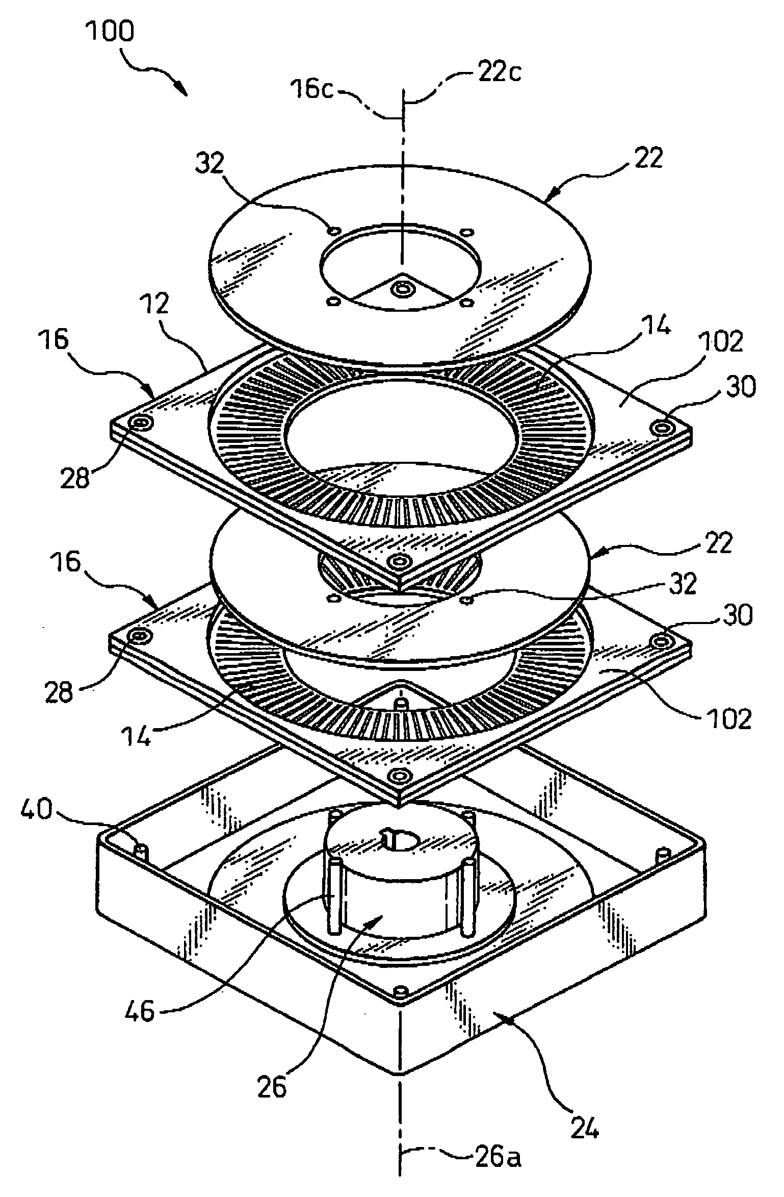
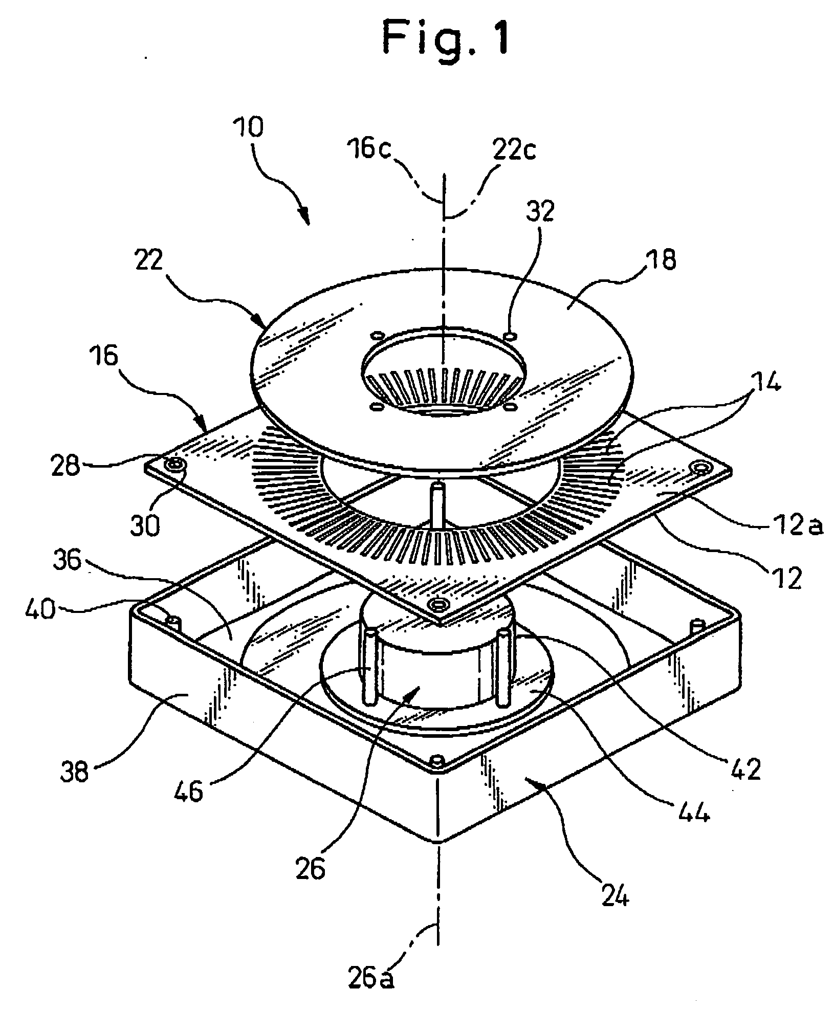
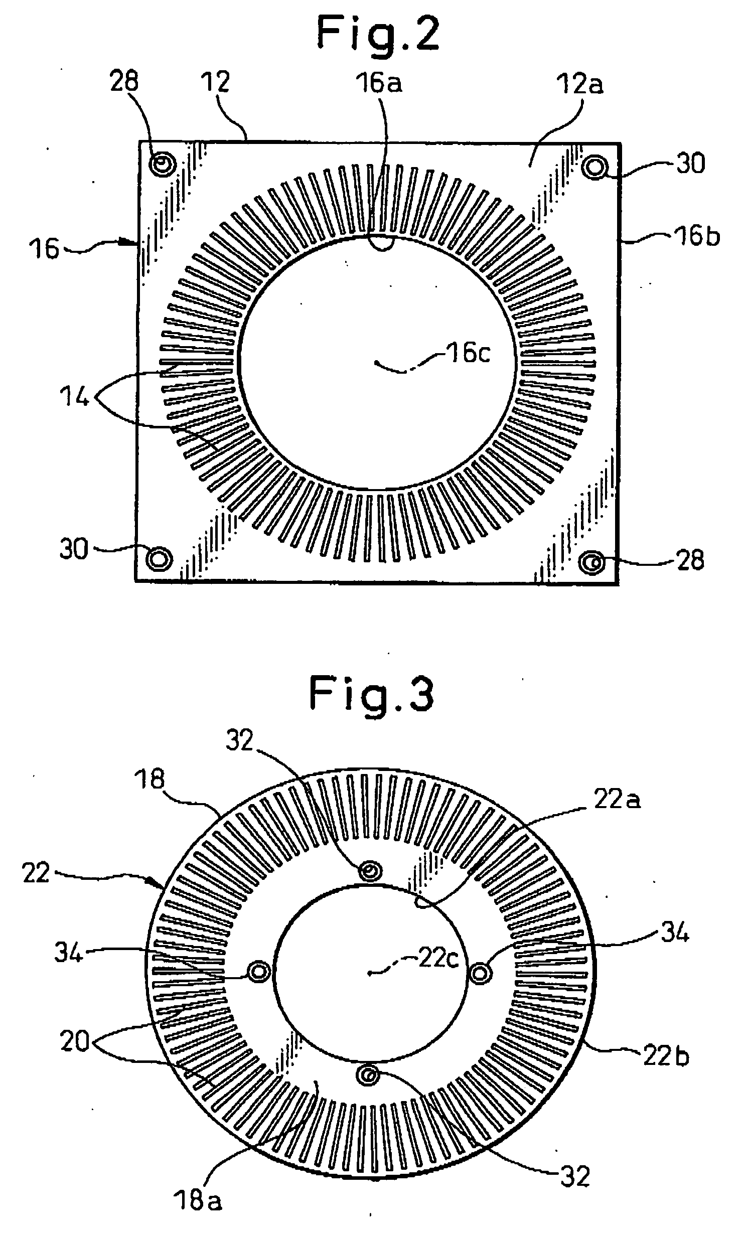
[0039] Referring to the drawings; FIG. 1 is an exploded perspective view showing the basic configuration of an electrostatic motor 10 according to an embodiment of the present invention; FIGS. 2 and 3 are plan views respectively showing two components of the electrostatic motor 10; FIGS. 4A to 4D and FIGS. 5A to 5C are views typically showing a manufacturing method, according to the present invention, for manufacturing the electrostatic motor 10.

[0040] As shown in FIG. 1, the electrostatic motor 10 includes a stationary member 16 having a plurality of electrodes 14 disposed at regular intervals on one surface 12a of an insulating substrate 12, a movable member 22 having a plurality of electrodes 20 (FIG. 3) disposed on one surface 18a of another insulating substrate 18, a first support member 24 for supporting the stationary member 16 in a fixed manner, and a second support member 26 for supporting the movable member 22 in a manner movable relative to the stationary member 16. Each ...

second embodiment

[0060] In the second embodiment, the insulating substrate 12 of the stationary member 16, as well as the adhesive layers 48 and the insulation layers 50, are made of a material having positive-type photosensitivity (FIG. 8A). The step of forming the mounting recess 28 includes exposing the local region 52 of the insulating substrate 12 to a light 60 with the light interrupting mark 30 being used as a mask (FIG. 5B), and thereafter chemically removing the local region 52 (FIG. 8C) by using a specified developer solution (not shown). According to this procedure, it is possible to accurately remove the local region 52 of the insulating substrate 12 while surely preventing the light interrupting mark 30 from being damaged.

[0061] As the light 60 for exposing the local region 52, ultra-violet radiation may be used, for which a photosensitive material, such as the insulating substrate 12, exhibits a high photon absorbency. Alternatively, in order to reduce an exposure time, a laser beam de...


PUM

PropertyMeasurementUnit
Shapeaaaaaaaaaa
Photosensitivityaaaaaaaaaa

Abstract

A method of manufacturing an electrostatic motor including a stationary member with electrodes disposed on an insulating substrate at regular intervals, a movable member with electrodes disposed on an insulating substrate at regular intervals, a first support member for fixedly supporting the stationary member, and a second support member for movably supporting the movable member. A plurality of electrodes are formed on one surface of an insulating substrate and, simultaneously therewith, a light interrupting mark is locally formed on the surface independently of the electrodes, to produce the stationary or movable member. A local region of the insulating substrate adjacent to the light interrupting mark is irradiated with a light, whereby removing the local region along an edge of the light interrupting mark without substantially damaging the light interrupting mark, to provide a mounting recess in the stationary or movable member. The stationary or movable member is mounted onto the corresponding first or second support member by using the mounting recess.

Description

BACKGROUND OF THE INVENTION [0001] 1. Field of the Invention [0002] The present invention relates to an electrostatic motor. The present invention also relates to a method of manufacturing an electrostatic motor. [0003] 2. Description of the Related Art [0004] An electrostatic motor including a stationary member having a plurality of electrodes disposed on one surface of an insulating substrate at regular intervals, a movable member having a plurality of electrodes disposed on one surface of another insulating substrate at regular intervals identical to the intervals of the electrodes of the stationary member, a first support member for supporting the stationary member in a fixed manner, and a second support member for supporting the movable member in a manner movable relative to the stationary member, is known. An electrostatic motor of this type is configured such that the stationary member is assembled to the movable member with the plurality of electrodes (generally strip-shaped...

Claims


Application Information

Patent Timeline
IPC IPC(8): H02N1/00B23K26/18B23K26/382
CPCY10T29/49009H02N1/004
Inventor ODAKA, SHUNICHIKARIYA, ISAO
Owner FANUC LTD
Why Eureka
Try Eureka