Radiating fin and method for manufacturing the same

a technology of radiation fins and fins, which is applied in the direction of cooling/ventilation/heating modifications, semiconductor/solid-state device details, semiconductor devices, etc., can solve the problem of small thermal resistance between carbon fiber and substra

Inactive Publication Date: 2006-03-30
FUJITSU LTD
View PDF4 Cites 13 Cited by
  • Summary
  • Abstract
  • Description
  • Claims
  • Application Information

AI Technical Summary

Benefits of technology

[0008] Another object of the present invention is to provide a radiating fin which can exert high cooling performance, and a method for manufacturing the same.
[0009] The radiating fin of the present invention is characterized in that, in a radiating fin in which a plurality of carbon fibers are provided on a substrate, the carbon fiber is plated with a metal, and a tip of the carbon fiber is brazed with a substrate. The radiating fin of the present invention is constructed such the carbon fiber having a surface plated with a metal is brazing-fixed on the substrate. Since the surface of the carbon fiber is plated with a metal, when brazing of the carbon fiber and the substrate is performed, the surface of the carbon fiber becomes easy to be wetted with a metal brazing material, the carbon fiber is easily fixed on the substrate, and mechanical connection between the carbon fiber and the substrate is firm. In addition, a thermal resistance between the carbon fiber and the substrate is small. For this reason, since after heat from electronic parts is transmitted to the substrate, the heat is transmitted to the carbon fiber with a very small thermal resistance, and the heat is radiated into the air from the surface of the carbon fiber, cooling performance is high.
[0010] In the radiating fin of the present invention, in the aforementioned construction, it is preferable that a material for metal plating is one or a plurality of metal(s) selected from a group consisting of Cu, Ni, Au, Sn, Ag, Pd and Pt, or an alloy containing one or a plurality of metal(s) selected from the group. In the radiating fin of the present invention, a surface of the carbon fiber is plated with one or a plurality of metal(s) of Cu, Ni, Au, Sn, Ag, Pd and Pt, or an alloy containing one or a plurality of metal(s) among these elements. Therefore, wettability between a brazing material for connection is better, and a thermal resistance between the carbon fiber and the substrate is very small.
[0011] In the radiating fin of the present invention, in the aforementioned construction, it is preferable that a material of the substrate is selected from a group consisting of Cu, Al and a ceramic. The substrate is constructed of a material having better heat conductivity such as Cu, Al, a ceramic and the like. Therefore, heat from electronic parts is effectively transmitted from the substrate to the carbon fiber.
[0012] The method for manufacturing a radiating fin of the present invention is a method for manufacturing a radiating fin in which a plurality of carbon fibers are provided on a substrate, comprising a step of subjecting a plurality of carbon fibers to metal plating treatment, a step of provisionally adhering one end of the metal-plated carbon fibers to a provisional substrate, and a step of brazing-fixing to a substrate the other end of the carbon fibers which is not provisionally adhered. After one end of the carbon fibers having a surface plated with a metal is provisionally adhered to the provisional substrate, the other end of the carbon fibers is brazing-fixed to the substrate to manufacture a radiating fin. Therefore, it is easy to manufacture a radiating fin having the aforementioned properties.
[0013] The method for manufacturing a radiating fin of the present invention is a method for manufacturing a radiating fin in which a plurality of carbon fibers are provided on a substrate, comprising a step of provisionally adhering one end of a plurality of carbon fibers to a provisional substrate, a step of subjecting the other end portion of the provisionally adhered carbon fibers to metal plating treatment, and a step of brazing-fixing the other end of the carbon fibers plated with a metal to a substrate. After one end of the carbon fibers is provisionally adhered to the provisional substrate, the other end portion of the carbon fibers is subjected to metal plating treatment, and the other end of carbon fibers is brazing-fixed to the substrate to manufacture a radiating fin. Therefore, it is easy to manufacture a radiating fin having the aforementioned properties.

Problems solved by technology

In addition, a thermal resistance between the carbon fiber and the substrate is small.

Method used


Image

  • Radiating fin and method for manufacturing the same
  • Radiating fin and method for manufacturing the same
  • Radiating fin and method for manufacturing the same

Examples


Embodiment Construction

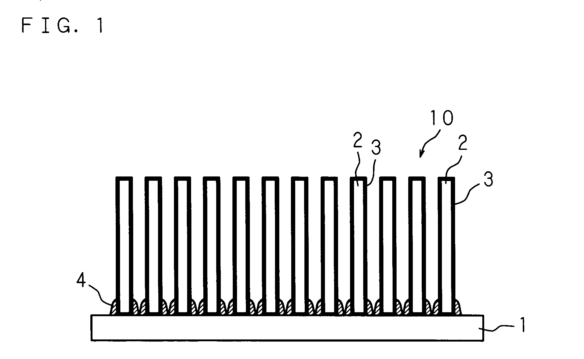
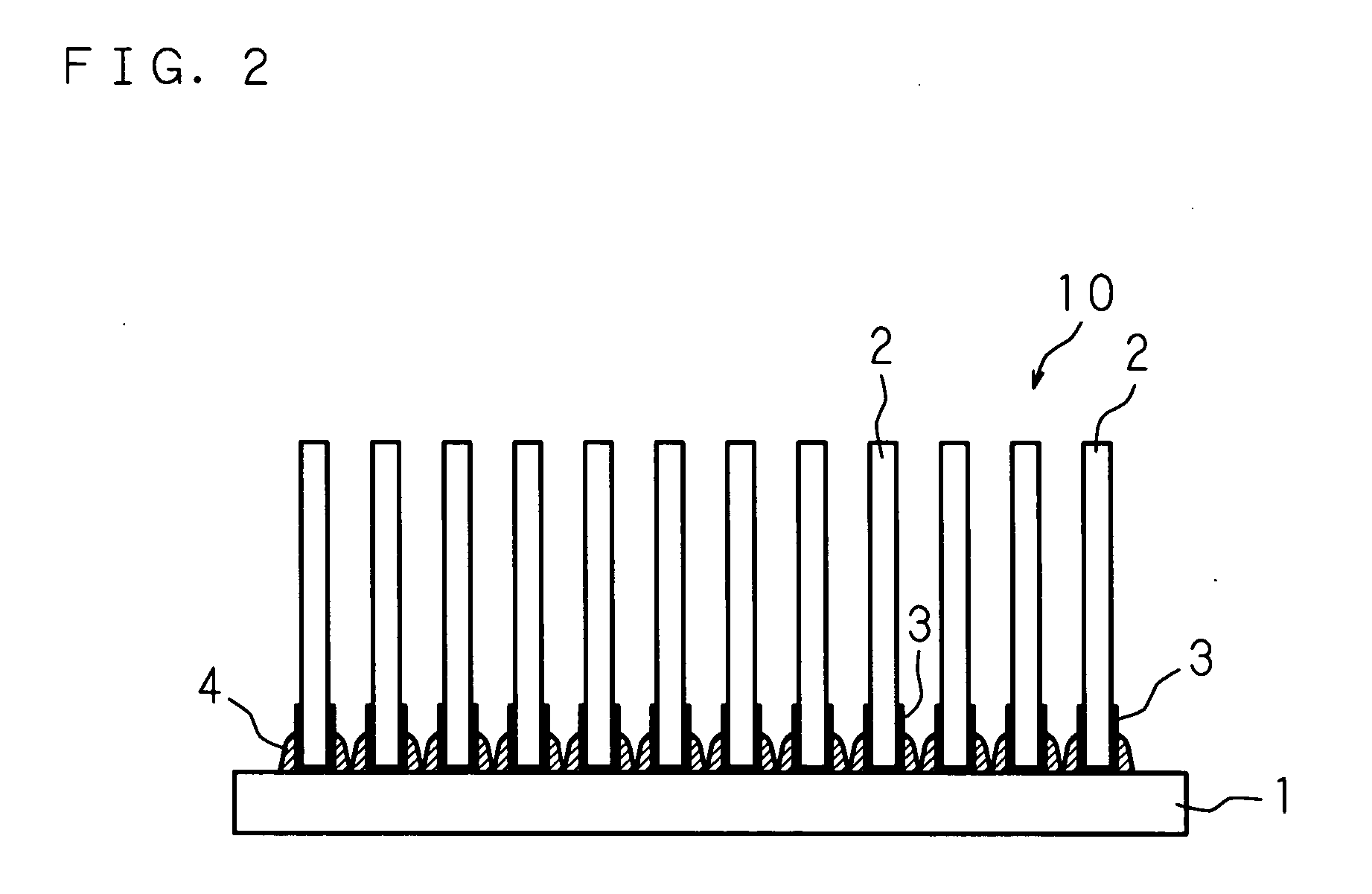
[0019] The present invention will be specifically explained below by referring to the drawings showing embodiments thereof. FIG. 1 is a view showing one example of construction of a radiating fin 10 of the present invention.

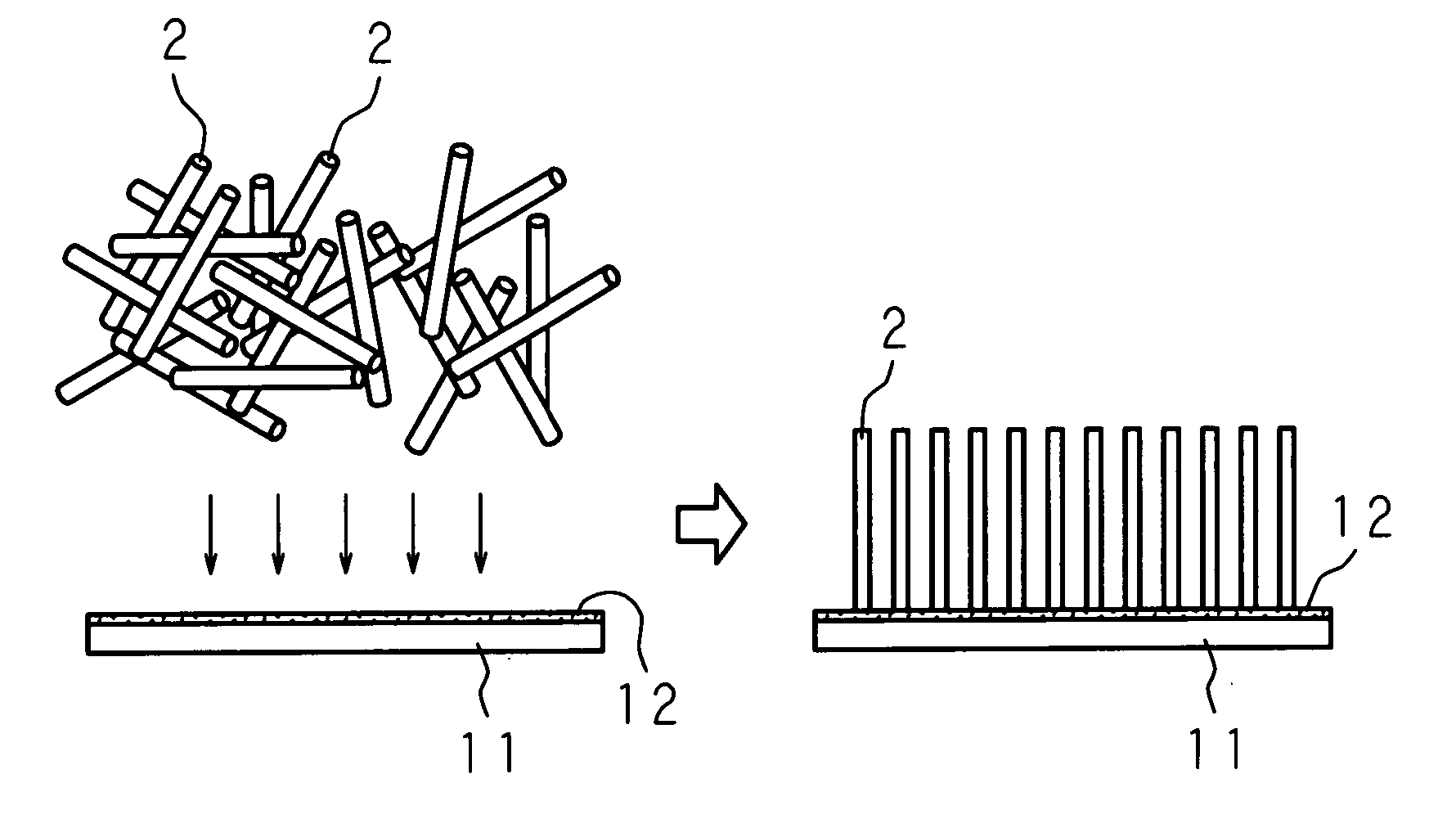
[0020] In FIG. 1, 1 is a substrate, for example, made of a Cu plate, and 2 is a plurality of carbon fibers having a surface having a metal-plated layer 3, for example, made of Cu. A tip of each carbon fiber 2 is adhered to the substrate 1 via a brazing material 4, for example, made of a solder.

[0021] As the carbon fiber 2, for example, Dialead (K223HG) manufactured by Mitsubishi Chemical Functional Products, Inc. may be used, but the carbon fiber is not limited to this as far as it is a carbon fiber having high heat conductivity. In addition, the carbon fiber 2 has a conversion diameter of 10 μm to 1 mm, and an aspect ratio of 5 to 100. When the carbon fiber 2 has such the size, it can be easily flown upon electrostatic flocking. As used herein, the “conversion...


PUM

PropertyMeasurementUnit
diameteraaaaaaaaaa
aspect ratioaaaaaaaaaa

Abstract

A plurality of carbon fibers having a surface having a metal-plated layer (Cu-plated layer) are stood vertically on a flat plate-like provisional substrate by electrostatic flocking, and one end of the carbon fibers is provisionally adhered to the provisional substrate with an adhesive. The other end of the carbon fibers which is not provisionally adhered is contacted with a substrate (Cu plate) having a surface coated with a solder paste and, in this state, a brazing material (solder) is melted and cooled, and carbon fibers and a substrate are brazed (soldered). After completion of mechanical and thermal connection between the substrate and the carbon fibers, this is immersed in an organic solvent, and the provisionally adhered provisional substrate is peeled from the carbon fibers to manufacture a radiating fin.

Description

CROSS-REFERENCE TO RELATED APPLICATION [0001] This nonprovisional application claims priority under 35 U.S.A. §119(a) on Patent Application No. 2004-284953 filed in Japan on Sep. 29, 2004, the entire contents which are hereby incorporated by reference.BACKGROUND OF THE INVENTION [0002] The present invention relates to a radiating fin which radiates heat produced by electronic parts such as computer CPU chips and the like in the air, and a method for manufacturing the same, in particular, a radiating fin using a pin fin made of a carbon fiber as a fin, and a method for manufacturing the same. [0003] In electronic devices in recent years, a heat value of electronic parts has been remarkably increased due to high integration and speedup, and it is necessary to effectively radiate heat produced from electronic parts to the outside. In order to effectively radiate heat from electronic parts into the air, it is effective to increase a radiating area. As an example of increase in a radiati...

Claims


Application Information

Patent Timeline
Patent Type & Authority Applications(United States)
IPC IPC(8): H01L23/053
CPCH01L21/4882H01L23/373H01L2924/0002H01L2924/00H05K7/20
Inventor UCHIDA, HIROKITOKUHIRA, HIDESHIISHINABE, MINORUDATE, HIROAKITANIGUCHI, JUN
Owner FUJITSU LTD
Why Eureka
Try Eureka