Substrate free flexible liquid crystal displays

a liquid crystal display and flexible technology, applied in non-linear optics, instruments, optics, etc., can solve the problems of reducing the overall efficiency of the light exiting the display, reducing the attractiveness of the display, and only useful devices for flat applications. , to achieve the effect of improving flexibility, reducing the number of layers, and expanding utility and us

Inactive Publication Date: 2006-03-30
IND TECH RES INST
View PDF77 Cites 82 Cited by
  • Summary
  • Abstract
  • Description
  • Claims
  • Application Information

AI Technical Summary

Benefits of technology

[0013] The present invention includes several advantages, not all of which are incorporated in a single embodiment. The present invention provides an “all coated” approach to making a liquid crystal, without the need for a support. The display may be formed on a transport sheet, which may also be referred to as a carrier sheet or substrate, or release liner and then transferred to an article, such as a supporting panel, that may be flat or shaped. This may allow for the formation of conformal displays. This invention does not require the use of a substrate and furthermore provides improved flexibility regarding where and how such displays can be used. Since this invention does not have a substrate, it may be used as a flat display or it may be formed in a curved or irregular shape. Such a display has expanded utility and use in a number of novel applications. Electronic displays can be used and conformed to a variety of articles that otherwise are not possible when thick, stiff substrates are used. The present invention also provides several display architectures in which there are a reduced number of layers and thereby improves the overall efficiency of the displays.

Problems solved by technology

While such a displays are useful, the use of several very stiff or nonflexible substrates makes this device only useful for flat applications.
Additionally such a display has numerous surface interfaces that can cause light scattering and absorption that reduces the overall efficiency of the light exiting the display.
Therefore customer will find this display less attractive.
Such displays suffer from low reflectivity because of the large number of substrate interfaces.
Additionally, such displays are very rigid and therefore not very flexible.
Such a display suffers from being very rigid and suffers from reduced optical clarity because of the large number of layer interfaces.
Each assembled display cells requires at least two substrates in order to form the display and therefore suffers from being not being flexible and also having numerous interface layers that will scatter light and reduces the displays overall efficiency.
Such a display also requires at least two substrates for each for each color and therefore suffers from the same problems as other full color displays.
While this display can produce color and has one less substrate, it cannot modulate each layer individually and therefore has limited use.
This process is designed for projection screen and contains any electrically modulated layers and therefore has limited usefulness for liquid crystal displays.
Approximately 10 volts / additional micron of thickness is need but there is a limit or the displays will not be functional.
Such displays will require very high voltages to switch and will be subject to burnouts and shorts.
Additionally the thicker layers of rein may further result in light scattering and less efficient displays.
If the amount of resin and liquid crystal is increased to provide a minimum amount of display stiffness, the liquid crystal layer become prohibitively expensive for a cost effective display.
Most polymers suitable for use in a liquid crystal layer do not have very high modulus of elasticity and therefore are not efficient means for eliminating substrates.

Method used


Image

  • Substrate free flexible liquid crystal displays
  • Substrate free flexible liquid crystal displays
  • Substrate free flexible liquid crystal displays

Examples


example 1

Control

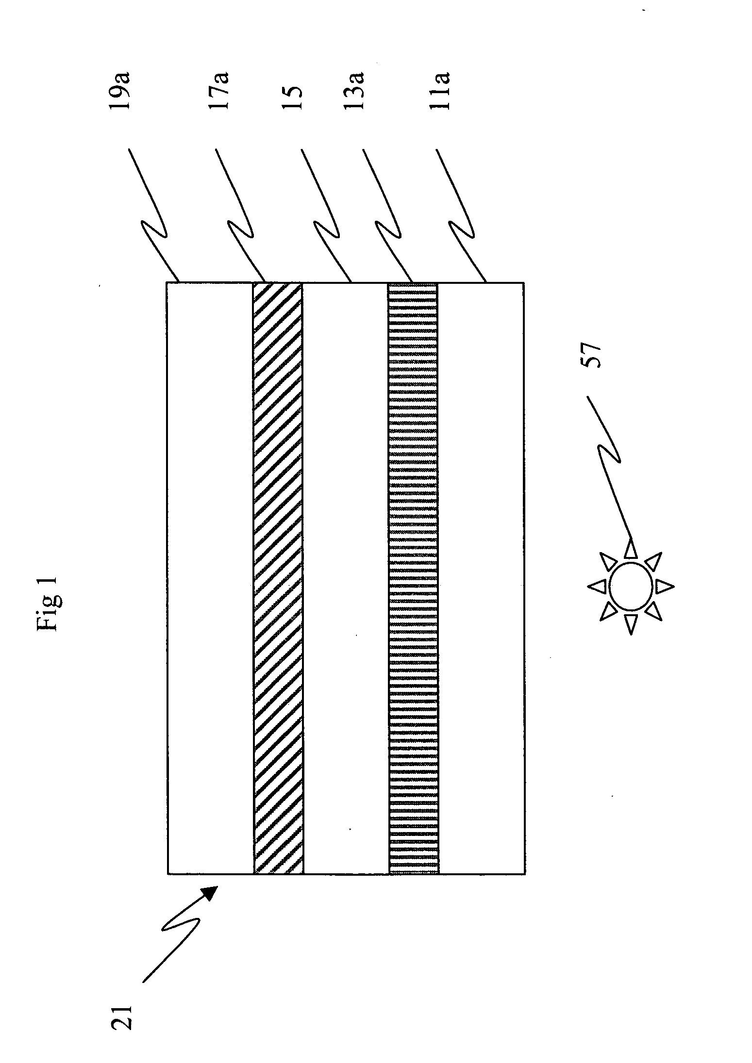
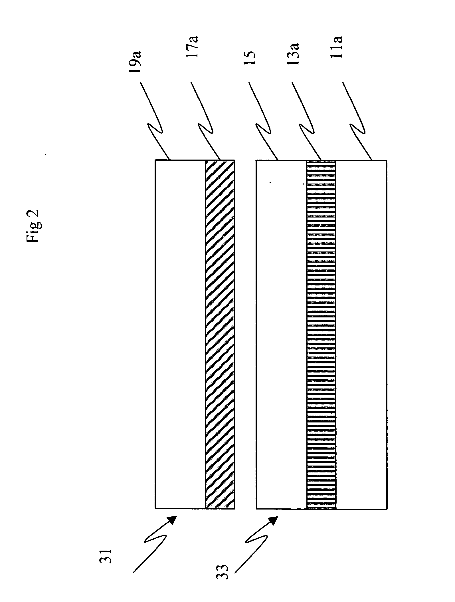
[0136] This example is shown in cross section in FIG. 1 in its laminated final form but was made from two separate webs (31 and 33) as shown by FIG. 2. Assembled display cell 33 was 125 micron, clear polyester substrate such as Dupont ST504 (11) and an ITO layer (13) of approximately 300 ohms / sq. The ITO was etched with a pulsed laser into a series of parallel line with approximately 3 mm spacing. The lines were in the machine direction of the web. The ITO was coated with an imageable layer containing gelatin and droplets of cholesteric liquid crystal as a separate web (31). A 4.7 mil clear polyester substrate (19) such as Dupont ST 504 was sputtered coated with a layer of ITO (17) in a vacuum deposited chamber. Such materials are commercially available from a number of ITO coaters such as Bekhart, CP Films, Sheldahl and Technimet. The ITO level was at approximately 300 ohms / sq. The ITO in web 31 was then etched with a pulsed laser with a series of parallel lines 90 degrees ...

example 2

Control

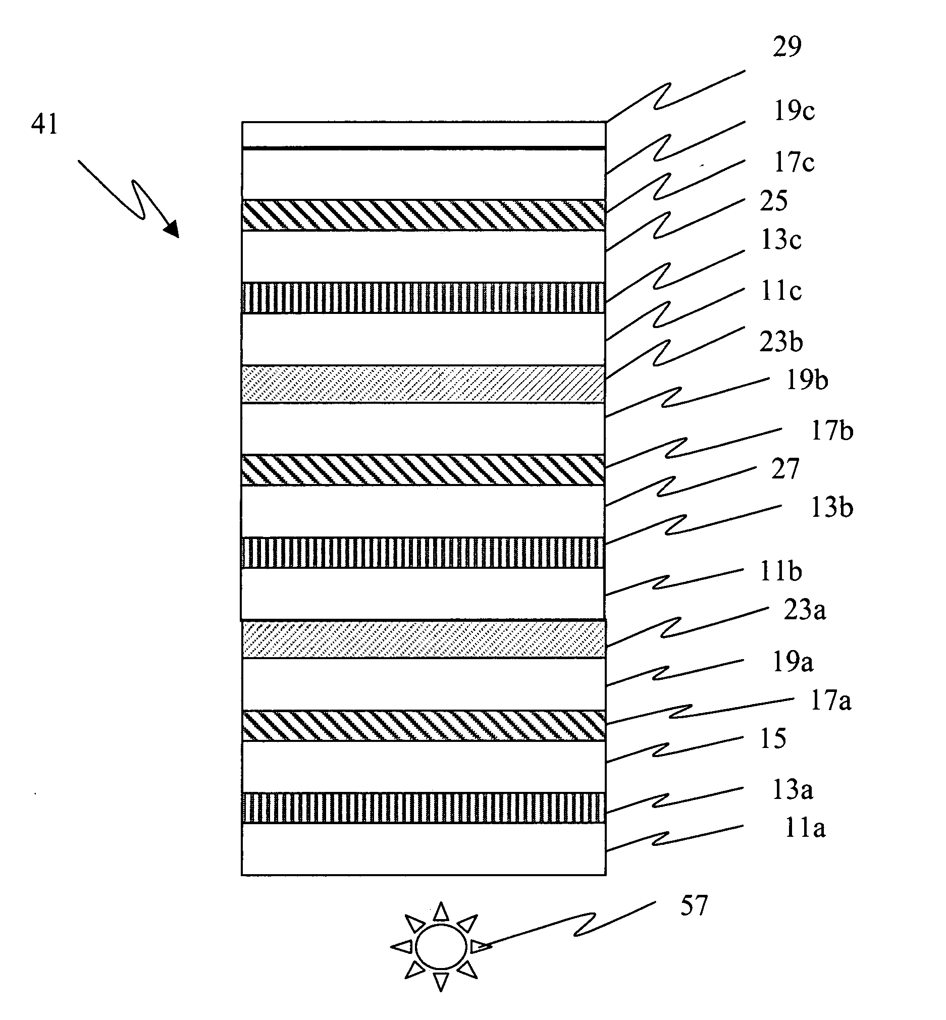
[0137] This example is shown in FIG. 4 and was made by forming three separate assembled display cells as described in example 1. The first assembled display cell was coated on a 125 micron clear polyester base with a imageable layer containing gelatin and droplets of blue cholesteric liquid crystal, the second assembled display cell was coated on a 125 micron clear polyester base with a imageable layer containing gelatin and droplets of green cholesteric liquid crystal and a third assembled display cell was coated on a 125 micron clear polyester base with a imageable layer containing gelatin and droplets of red cholesteric liquid crystal. Once the three assembled display cells were formed, they were adhered together by placing a strip of optically clear adhesive such as 3M 8142 (approximately 25 micron thick) between assembled display cells 1 and 2 and then between the second and third assembled display cell. Such a configuration forms a stacked three-color liquid assembled ...

example 3

[0138] This example (cross section shown in FIG. 5) was made similar to example 2 except layers 19c (top clear conductive layer) and 29 (black absorbing layer) were replaced with a printed layer patterned colored conductor, resulting in one less substrate as compared to Example 2. In this case a UV curable ink containing conductive carbon was patterned with a parallel line spacing. The layer had a conductivity of approximately 250 ohms / sq. This display had a minimum of 17 layers.


PUM

PropertyMeasurementUnit
adhesive strengthaaaaaaaaaa
adhesionaaaaaaaaaa
adhesionaaaaaaaaaa

Abstract

The present invention relates to a flexible multi-color display comprising an optional substrate, at least one independently switchable electrically modulated imaging layer between an upper conductive layer and a lower conductive layer, wherein the number of said optional substrate is less than or equal to the number of said at least one independently switchable electrically modulated imaging layer. The present invention also relates to a display comprising portions of a flexible multi-color displays produced separately and laminated to gether to form a final display, as well as displays having removable carrier/transport substrates and methods for making the same.

Description

FIELD OF THE INVENTION [0001] The present invention relates to full color electrochromic and chiral doped cholesteric liquid crystal displays their design and method of making. BACKGROUND OF THE INVENTION [0002] Cholesteric displays are bistable in the absence of a field, the two stable states being the reflective planar state and the weakly scattering focal conic state. In the planar state, the helical axes of the cholesteric liquid crystal molecules are substantially parallel to the substrates between which the liquid crystal is disposed. In the focal conic state the helical axes of the liquid crystal molecules are generally randomly oriented. By adjusting the concentration of chiral dopants in the cholesteric material, the pitch length of the molecules and thus, the wavelength of radiation that they will reflect, can be adjusted. Cholesteric materials that reflect infrared radiation have been used for purposes of scientific study. Commercial displays are fabricated from cholester...

Claims


Application Information

Patent Timeline
Patent Type & Authority Applications(United States)
IPC IPC(8): G02F1/1333
CPCG02F1/133305G02F1/13473G02F2202/22G02F2001/13613G02F2001/13478G02F1/13478G02F1/13613
Inventor AYLWARD, PETER T.MONTBACH, ERICA N.
Owner IND TECH RES INST
Why Eureka
Try Eureka