Circuit arrangement and method for determining a frequency drift in a phase locked loop

Inactive Publication Date: 2006-03-30
INTEL CORP +1
View PDF6 Cites 14 Cited by
  • Summary
  • Abstract
  • Description
  • Claims
  • Application Information

AI Technical Summary

Benefits of technology

[0015] A circuit can be connected upstream of the counting input of the device, said circuit being designed for changing a plurality of the output signal of the oscillator depending on a control signal. This increases the accuracy of the measurement and avoids systematic errors occurring during the measurement, in particular. In another refinement, this circuit is formed with a logic XOR gate (non-equivalence gate), a first input of the XOR gate being connected to the signal output of the oscillator. The control signal is present at the second input.
[0016] The device can, in another example, comprise a shift register, which is coupled to the output of the phase comparator on the input side. This shift register serves for repeated measurement of th

Problems solved by technology

This solution has the disadvantage, however, that the frequency information has to be transferred through the loop filter of the phase locked loop.
A normal loop filter generates errors in the modulation, however, as a result of its transfer response.
The disadvantage of a type I phase locked loop with a nonintegrating loop filter consists,

Method used


Image

  • Circuit arrangement and method for determining a frequency drift in a phase locked loop
  • Circuit arrangement and method for determining a frequency drift in a phase locked loop
  • Circuit arrangement and method for determining a frequency drift in a phase locked loop

Examples


Example

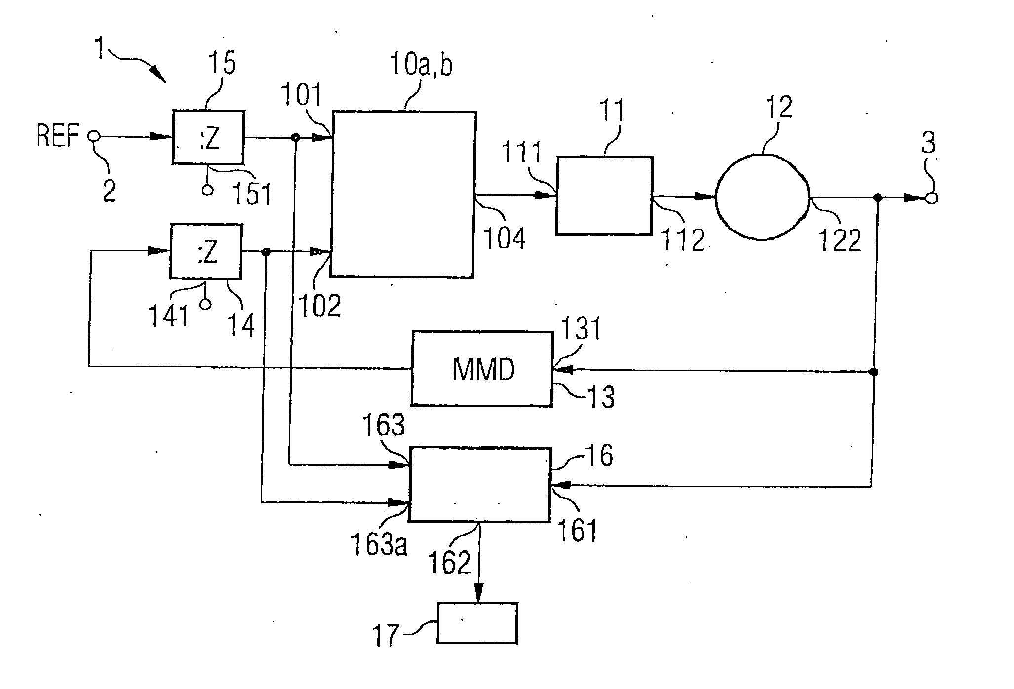
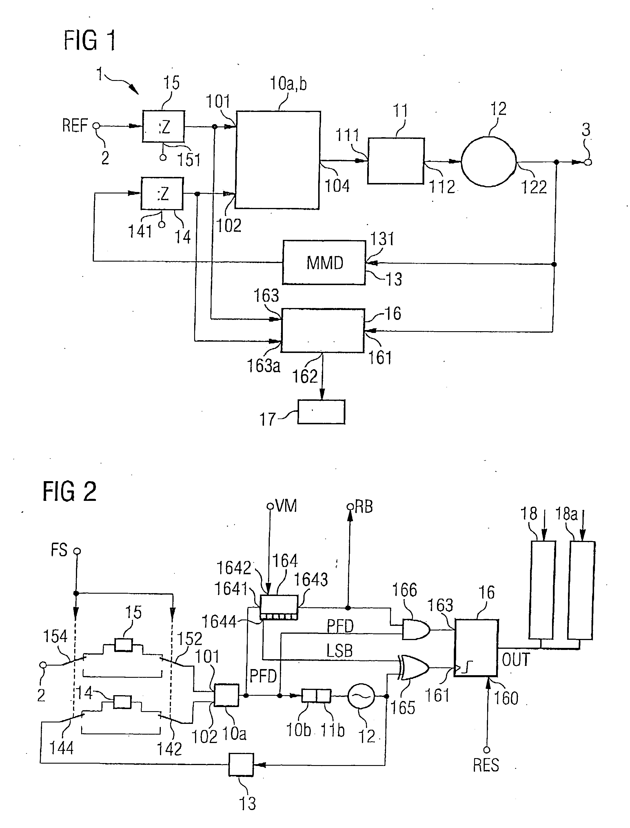
[0032]FIG. 1 shows a circuit arrangement according to the invention in a first aspect or embodiment. The phase locked loop 1—illustrated therein—with the measuring and computing unit provided for determining a frequency and phase drift of the output signal of the oscillator can be used in mobile radio devices or mobile communication systems.

[0033] The aspect or embodiment illustrated in FIG. 1 comprises a signal input 2, to which a reference signal REF is fed, and also a signal output 3, at which a frequency-stable output signal can be tapped off. In accordance with the principle proposed, a phase comparator 10a, which is illustrated here together with a charge pump 10b, is connected to a loop filter 11 on the output side. The output 112 of the loop filter 11 is connected to an actuating input of a voltage controlled oscillator 12. On the output side, the oscillator forms the signal output 3 of the control loop. Furthermore, the signal output 122 of the oscillator 12 is connected t...


PUM


Abstract

A circuit arrangement for determining a frequency drift in a phase locked loop includes a type I phase locked loop having a phase comparator, a charge pump, a loop filter, an oscillator and also a frequency divider in a feedback path of the control loop. A device is coupled to the phase locked loop for the purpose of determining a pulse length of the actuating voltage signal at at least two different times during an operation of the control loop. Furthermore, a computing unit is connected to an output of the device. It is designed for forming a difference between the pulse lengths at the at least two different times, as a result of which a phase and frequency drift of an output signal of the control loop can be determined.

Description

REFERENCE TO RELATED APPLICATIONS [0001] This application claims the benefit of the priority date of German application DE 10 2004 046 404.9, filed on Sep. 24, 2004, the contents of which are herein incorporated by reference in their entirety. FIELD OF THE INVENTION [0002] The invention relates to a circuit arrangement for determining a frequency drift of an output signal in a phase locked loop. The invention furthermore relates to a method for determining a frequency drift in a phase locked loop. BACKGROUND OF THE INVENTION [0003] Phase locked loops are usually used for generating frequency-stable signals. The signals provided serve for example as a local oscillator signal in a transmission path of a mobile communication device. [0004] Depending on the mobile communication standard used, it is also possible, however, to embody phase locked loops for a direct modulation, in which the output signal of an oscillator of the control loop is modulated directly. This is expedient primaril...

Claims


Application Information

Patent Timeline
IPC IPC(8): H03D3/24
CPCH03L7/193
Inventor CAMUFFO, ANDREA
Owner INTEL CORP
Why Eureka
Try Eureka