
Optical fiber/waveguide polarizer and method of fabrication

Inactive Publication Date: 2006-03-30
HER MAJESTY THE QUEEN & RIGHT OF CANADA REPRESENTED BY THE MIN OF IND THROUGH THE COMM RES CENT
View PDF12 Cites 20 Cited by
  • Summary
  • Abstract
  • Description
  • Claims
  • Application Information

AI Technical Summary

Benefits of technology

[0061] one or more sections of the optical fiber that include periodic/aperiodic (chirped, quasi-periodic) modulation of the dielectric properties of the fiber in the direction of propagation of the light (the longitudinal axis of the fiber). The modulation of t

Problems solved by technology

These devices are complex and expensive and suffer from an index of refraction mismatch with optical fiber waveguides.
However, such a device has some intrinsic limitations.
It is well known that bridging losses increase with separation between optically connected waveguides.
Therefore, the maximum thickness of polarizing dichroic material that can be used is limited by the need to ensure that the bridging losses between the waveguides are kept below an acceptable value.
The micro-optic approach suffers from the need to maintain critical alignment of all the optical components that comprise it.
Furthermore, the devices are relatively bulky in practice.
Optical fiber that is tightly wound around a mandrel suffers from radiation losses.
This device is bulky and suffers from performance limitations including narrow-bandwidth operation.
In practice these polarizers suffer from poor extinction ratio and are usually narrowband in operation.
Although Kim's device appears to perform its intended function, it is thought to be less than optimal as it is based on mechanically deforming the fiber to achieve these results.
There are several disadvantages to devices fabricated using this structure and process.
This compromises the precise control of the process, primarily the stress magnitude and the repeatability, thereby potentially reducing the reliability and manufacturing yield.
Furthermore, using an electric discharge arc for locally heating the optical fiber has certain positional precision problems associated with it.
It is also known that microbends cause scattering or out-coupling of both polarisation states from the optical fiber, which tends to increase the overall insertion loss in the device.
As Gambling et al. describe in Optical and Quantum Electronics Vol. 11, pages 43-59, 1979, not only does the radius of curvature of the microbend affect the bending loss, but also the transition from a straight portion of fiber to a curved portion can give rise to additional loss, known as “transition loss” due to mode conversion and energy redistribution.
Controlling the geometry of such transitions requires a very complex fabrication process, which may not be practical for commercial manufacturing.
It is important to note that while both types of the above losses posses some polarization dependence which can be utilized for the fabrication, both add to the overall losses in the device.
Finally, in the finished device the microbends created in the fabrication process constitute discontinuities in the fiber profile, probably creating mechanical stress concentration spots as well as points of residual stress, whereby the device reliability and robustness is impacted negatively.
Putting a birefringent material between crossed polarizers can give rise to interference colors.
Thus the applied tensile or compressive stress leads to stress-induced birefringence in the material.

Method used


Image

  • Optical fiber/waveguide polarizer and method of fabrication
  • Optical fiber/waveguide polarizer and method of fabrication
  • Optical fiber/waveguide polarizer and method of fabrication

Examples


Embodiment Construction

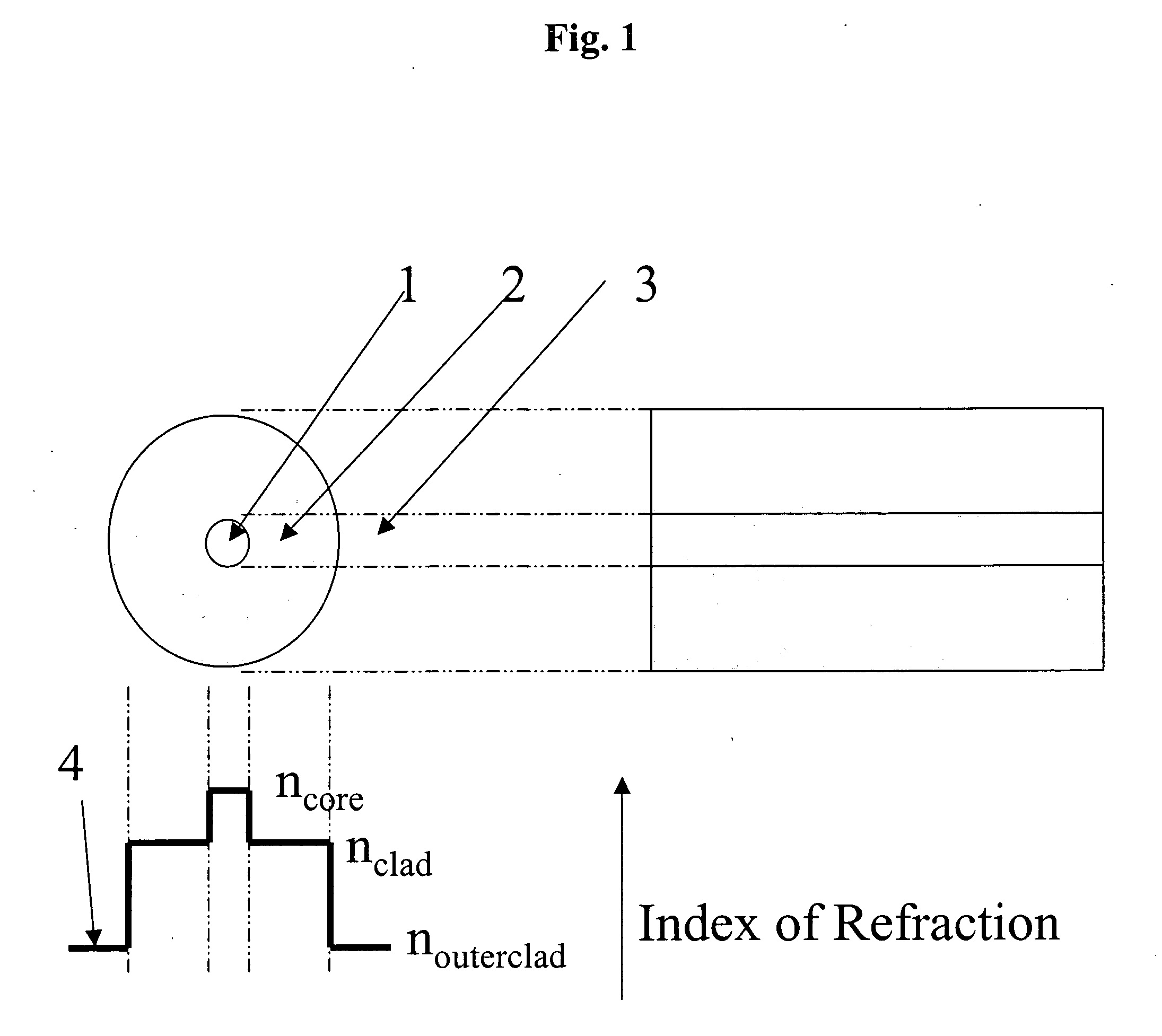
[0069] A typical prior art single mode optical fiber is presented in FIG. 1 together with a schematic cross-section of the fiber. Three regions within the fiber can be distinguished: [0070] a) the fiber core 1 with refractive index ncore; [0071] b) the fiber cladding 2 with refractive index nclad; [0072] c) the outer fiber cladding 3 with refractive index nouteclad.

[0073] The refractive index profile 4 illustrates the approximate relative magnitudes in refractive index of the three regions.

[0074] When an optical wave propagates along the fiber, the associated electromagnetic field of the optically guided modes extend over the core 1, the cladding 2 and the outer cladding 3 where present. Each mode is characterized by a size, known as the optical mode spot size, which is typically measured between the points where the electromagnetic field intensity is at half the value of the peak intensity.

[0075] The central requirement for ensuring that there is minimal coupling to cladding mod...


PUM


Abstract

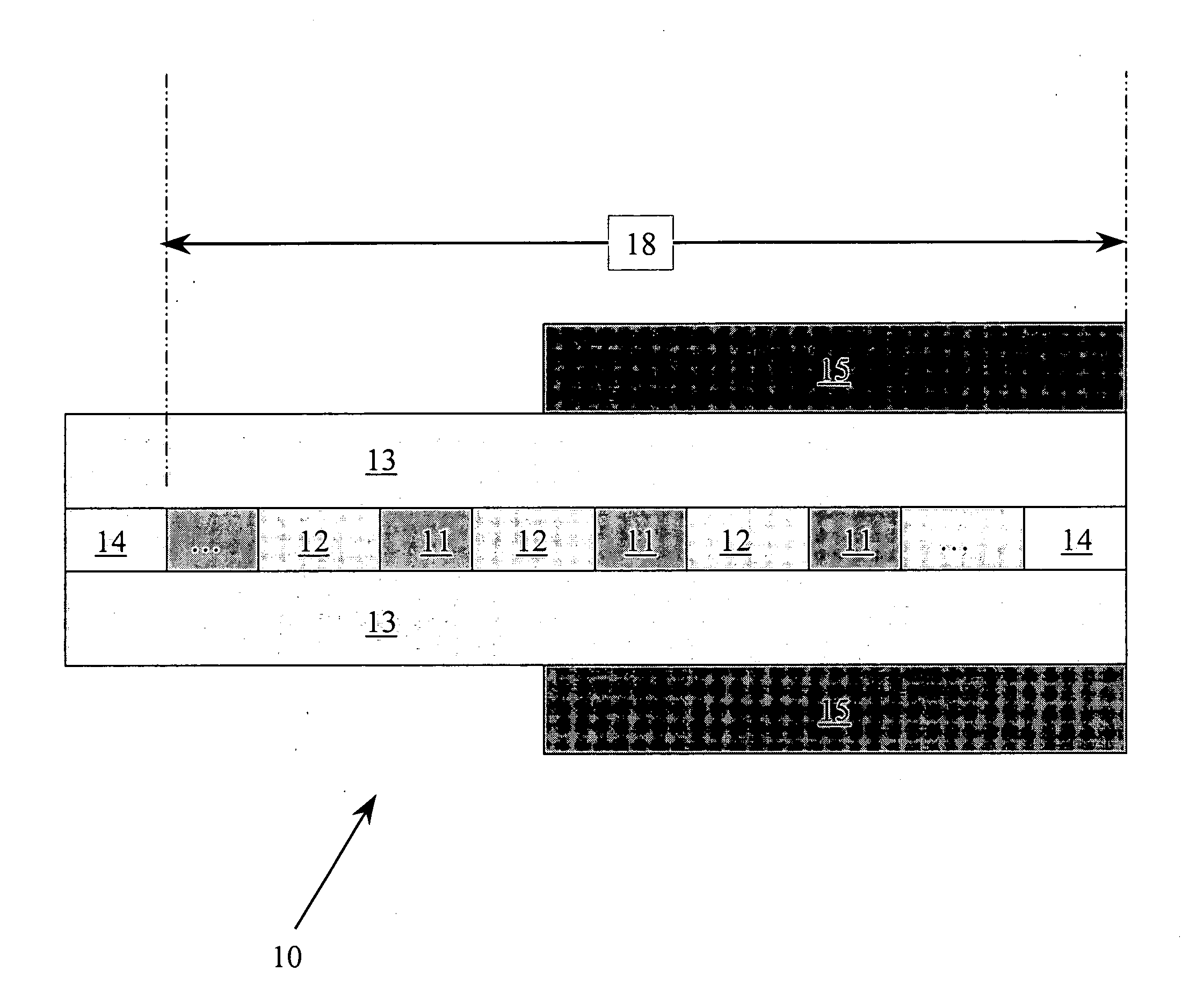
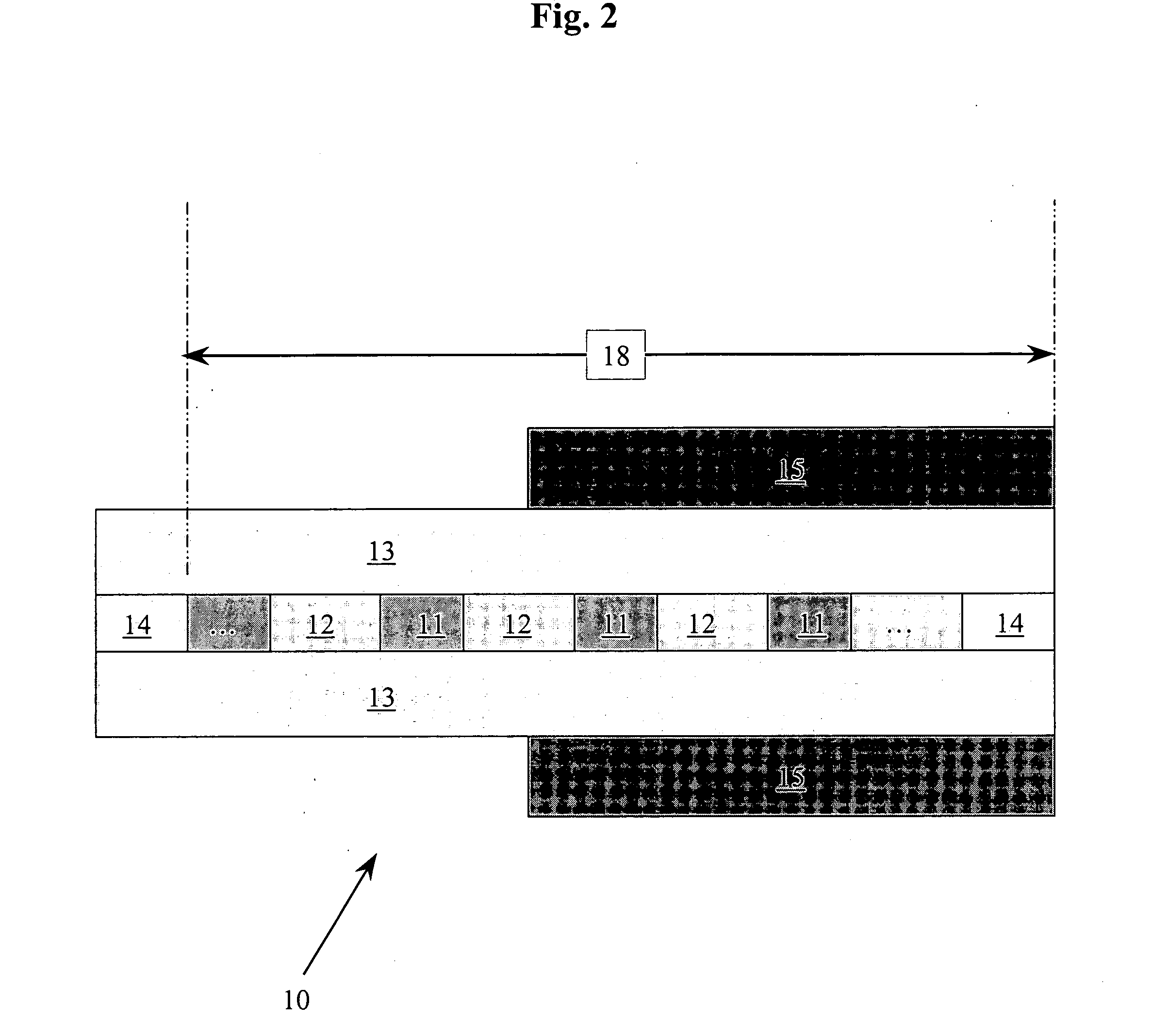
The invention relates to an optical fiber polarizer comprising an optical fiber with at least a core, a cladding and surrounding medium (or outer cladding) where one or more sections of the optical fiber include periodic / aperiodic (chirped, quasi-periodic) modulation of the dielectric properties of the fiber in the direction of propagation of the light (the longitudinal axis of the fiber). The modulation of the dielectric properties of the fiber is such that it introduces periodic / aperiodic birefringence along the direction of propagation of the light, such a modulation usually but not necessarily being confined to the vicinity of the core region of the fiber. Means are included to attenuate preferentially some of the modes of propagation of the fiber, specifically modes of one principal state of polarization and not the orthogonal state of polarization.

Description

CROSS-REFERENCE TO RELATED APPLICATIONS [0001] The present invention claims priority from U.S. Provisional Patent Application No. 60 / 612,948 filed Sep. 27, 2004, which is incorporated herein by reference.TECHNICAL FIELD [0002] The present invention relates to optical media, such as optical fibers and optical waveguides, and particularly to an optical fiber / waveguide structure that functions as an optical fiber / waveguide core-mode polarizer. BACKGROUND OF THE INVENTION [0003] Polarizers are well known devices in classical optics, and are used to preferentially attenuate light / electromagnetic radiation polarized in one direction (along one of the principal polarization axes of the polarizer) and allow transmission of the orthogonally polarized radiation. [0004] There are several types of polarizers available including: [0005] i) prism polarizers, such as the Glan-type prism polarizers and the Nicol-type prism polarizers, [0006] ii) polarizing beam splitters, such as the Rochon, Senarm...

Claims


Application Information

Patent Timeline
IPC IPC(8): G02B6/34G02B6/00G02B6/10
CPCG02B6/105G02B6/02076
Inventor HILL, KENNETH O.
Owner HER MAJESTY THE QUEEN & RIGHT OF CANADA REPRESENTED BY THE MIN OF IND THROUGH THE COMM RES CENT
Learn More