Methods and apparatus for aerodynamically self-enhancing rotor blades

a technology of rotor blades and aerodynamics, applied in the direction of machines/engines, supersonic fluid pumps, liquid fuel engines, etc., can solve problems such as instabilities in aerodynamics, and achieve the effect of improving aerodynamic performan

Inactive Publication Date: 2006-03-30
GENERAL ELECTRIC CO
View PDF28 Cites 14 Cited by
  • Summary
  • Abstract
  • Description
  • Claims
  • Application Information

AI Technical Summary

Benefits of technology

[0009] The present invention provides further improvements in aerodynamic performance over known configurations. Thus, in one aspect, the present invention provides an airfoil having a root, a tip, and an outer surface for pressuring air flowable thereover. The outer surface includes one or more slots elongate in a direction selected to preclude or reduce circulation within the slots, and the one or more slots are configured to bleed a boundary layer from the outer surface to the tip utilizing one or more passageways within the airfoil.

Problems solved by technology

Incurred losses are passed on to downstream blading in the form of wakes and vortices that interact with the downstream blading to create further losses, possible aerodynamic instabilities, and noise.

Method used


Image

  • Methods and apparatus for aerodynamically self-enhancing rotor blades
  • Methods and apparatus for aerodynamically self-enhancing rotor blades
  • Methods and apparatus for aerodynamically self-enhancing rotor blades

Examples


Embodiment Construction

[0027] As used herein, the term “blade” is used to refer to a type of airfoil suitable for use in conjunction with a rotor. However, the present invention is not limited to blades and is more generally applicable to all types of airfoils.

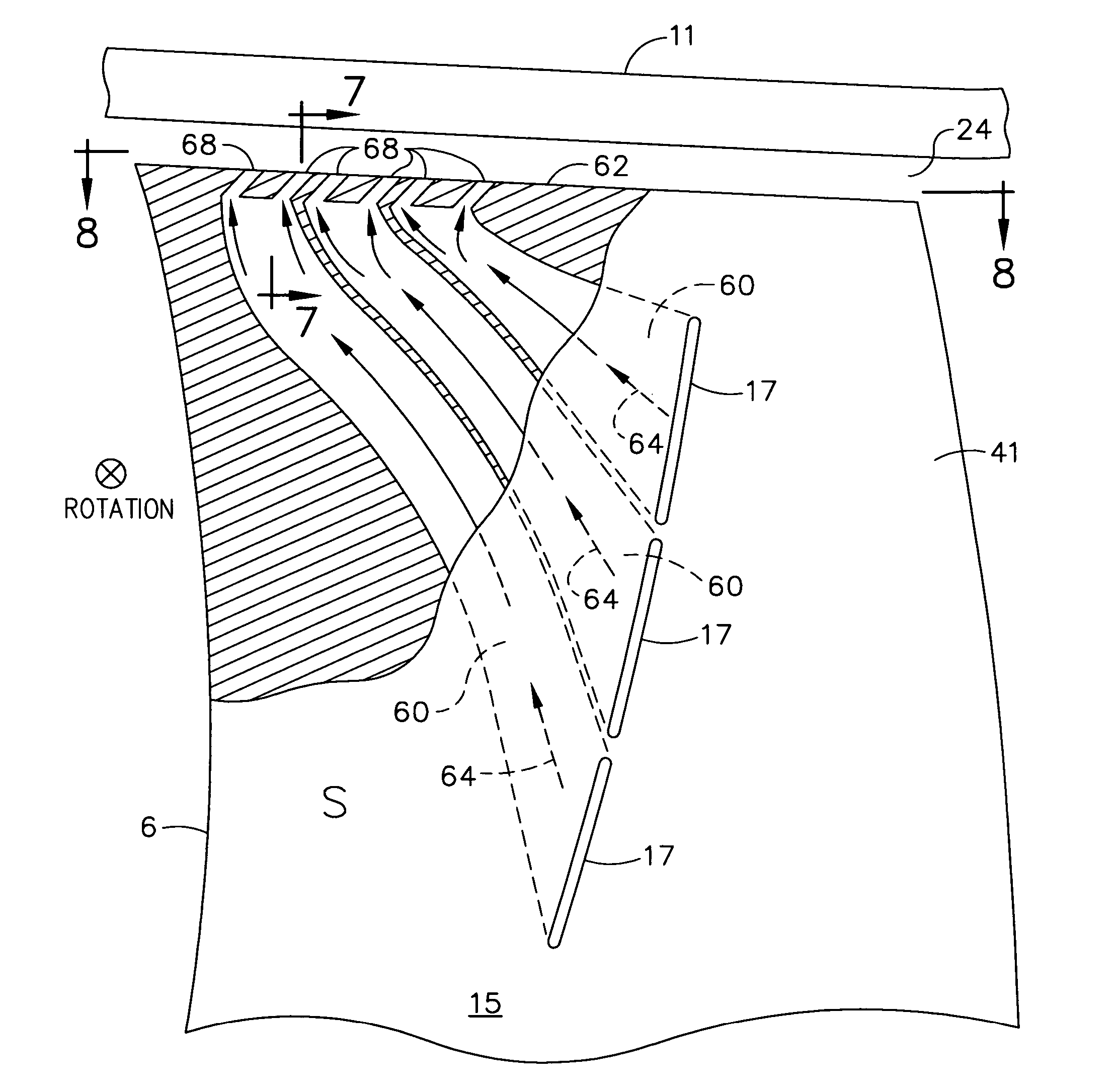
[0028] Various configurations of the present invention utilize available centrifugal energy of a rotor to remove, invigorate, and reingest blade and hub surface boundary layers to thereby improve performance, aerodynamic stability, and noise generation of a compression component. More specifically, a portion of the lossy blade and hub surface boundary layer is bled off, pumped up, and channeled through a hollowed out region of the blade. This boundary layer in some configurations is re-ingested into the main flow for the added purpose of redirecting and mixing with tip clearance flow and / or blowing the trailing edge wake. Configurations of the present invention are particularly useful for swept blading, in which surface boundary layers are pooled a...


PUM


Abstract

An airfoil having a root, a tip, and an outer surface for pressuring air flowable thereover. The outer surface includes one or more slots elongate in a direction selected to preclude or reduce circulation within the slots, and the one or more slots are configured to bleed a boundary layer from the outer surface to the tip utilizing one or more passageways within the airfoil.

Description

BACKGROUND OF THE INVENTION [0001] This invention relates generally to methods and apparatus for increasing efficiency of airfoils, and more particularly to methods and apparatus for extracting from boundary layers of airfoils. [0002] A gas turbine engine such as that configured for powering an aircraft in flight conventionally includes in serial flow communication a fan, a compressor, a combustor, a high pressure turbine (HPT), and a low pressure or power turbine (LPT). Ambient air enters the fan wherein it is initially pressurized, and in turn a portion thereof flows to the compressor wherein it is further pressurized and discharged to the combustor wherein it is mixed with fuel and ignited for generating hot combustion gases which flow downstream to the HPT. The HPT includes one or more stages of turbine blades specifically configured for extracting energy from the combustion gases for powering the compressor through a shaft connected therebetween. The combustion gases lose press...

Claims


Application Information

Patent Timeline
Patent Type & Authority Applications(United States)
IPC IPC(8): F01D5/18F04D21/00F04D29/68
CPCF04D29/681F04D21/00F04D29/682F04D29/684F01D5/145F01D5/20F05D2270/17F05D2270/173Y02T50/60F04D29/324F04D29/384F15D1/12
Inventor WADIA, ASPI RUSTOMSZUCS, PETER NICHOLASKHALID, SYED ARIFWOOD, PETER JOHNKIRTLEY, KEVIN R.LIU, XIAOYUE
Owner GENERAL ELECTRIC CO
Why Eureka
Try Eureka