
Device and method for removal of preforms

a technology of preforms and devices, applied in the field of preform removal, can solve the problems of inability to easily remove the preform from the core of the injection molding apparatus, inability to easily remove the preform, and inability to manufacture tools, etc., to achieve the effect of reducing the cycle time of molds, reducing the cost of replacing these softer cores, and reducing the cost of replacemen

Inactive Publication Date: 2006-03-30
GRAHAM PACKAGING CO LP
View PDF6 Cites 2 Cited by
  • Summary
  • Abstract
  • Description
  • Claims
  • Application Information

AI Technical Summary

Benefits of technology

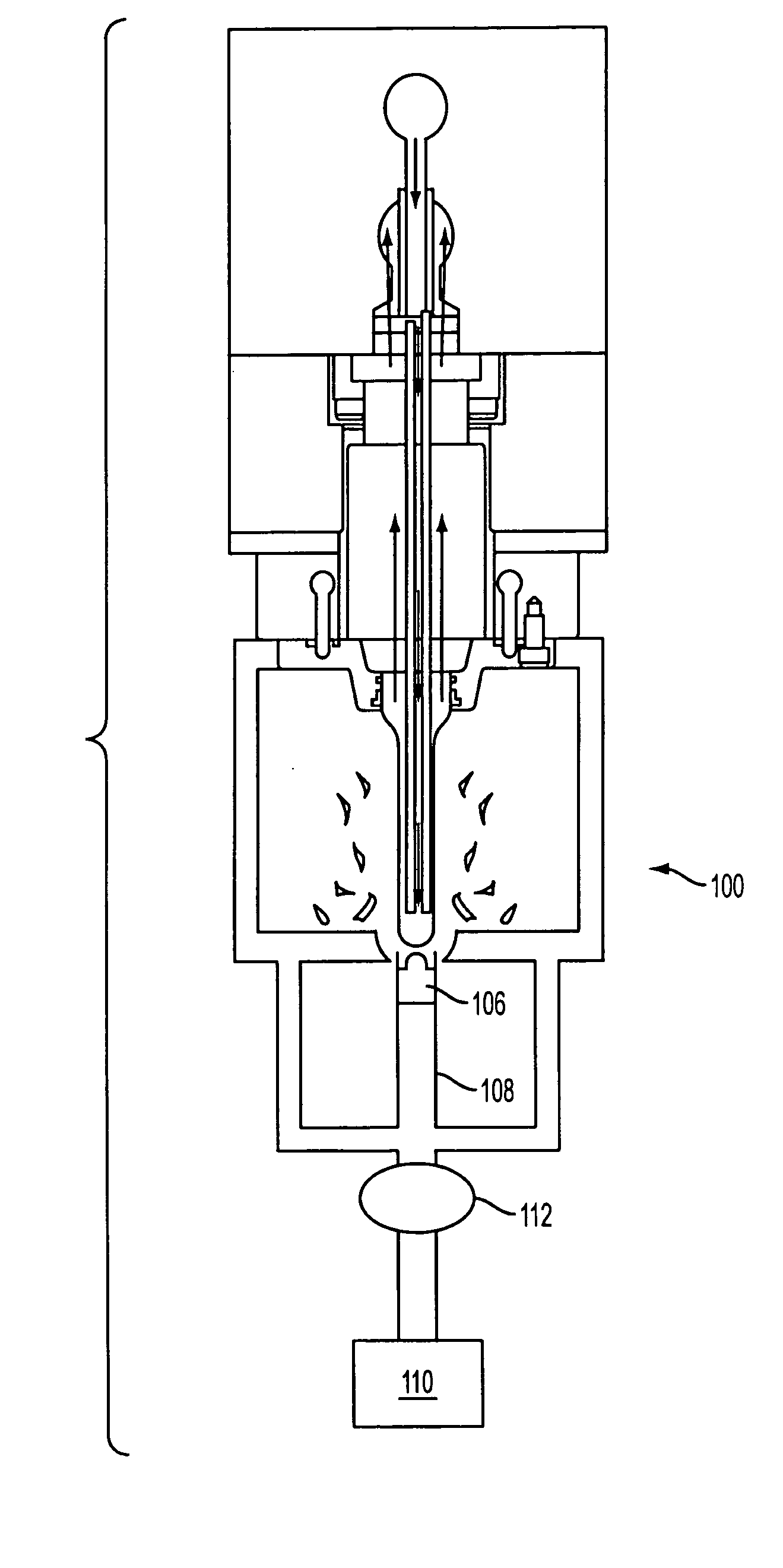
The present invention is a device and method for fracturing defective preforms in blowmolding processes. The device includes a tube with a cavity for accepting the defective preform and an attachment element for attaching it to an injection molding apparatus. The device also has a percussion instrument for contacting and breaking the preform at the tail end. The percussion instrument moves in a direction aligned with the core of the injection molding apparatus. The invention allows for the use of ampcoloy cores, which decrease cycle time and improve efficiency, while also providing a cost-effective method for removing defective preforms.

Problems solved by technology

Preforms created in the injection molding process are sometimes defective in that they cannot be easily removed from the core of the injection molding apparatus over which the preforms are shaped.
However, ampcoloy cores are softer than steel and are very susceptible to damage when struck with a hammer.
Using a hammer to remove a defective preform creates a likelihood that the core will bend when struck.
A bent core cannot be straightened, so it must be replaced at significant cost.
One difficulty in using a brass hammer, regardless of the core with which it is used, it that the defective preform must be struck with just the right force.
This may require multiple attempts.
There is also a chance that the plastic will shatter, making clean-up tedious, time consuming, and potentially dangerous.
Further, the process requires the use of man-power, which increases costs.
This loss of time results in lower productivity, and ultimately, a reduction in efficiency.
The problem with this method is that is requires alignment of the platen with multiple cores, the platen is large and cumbersome, and if the platen is not pulled down at the proper angle, the ampcoloy core can bend.
Furthermore, platens are heavy, and require the use of an additional machine to put the platen into place and to remove it.

Method used


Image

  • Device and method for removal of preforms
  • Device and method for removal of preforms
  • Device and method for removal of preforms

Examples


Embodiment Construction

[0024] Embodiments of the invention are discussed in detail below. In describing embodiments, specific terminology is employed for the sake of clarity. However, the invention is not intended to be limited to the specific terminology so selected. While specific exemplary embodiments are discussed, it should be understood that this is done for illustration purposes only. A person skilled in the relevant art will recognize that other components and configurations can be used without parting from the spirit and scope of the invention. All references cited herein are incorporated by reference as if each had been individually incorporated.

[0025] To appreciate the workings of the present invention, it is necessary to first understand the removal process for a fully-developed, functional preform.

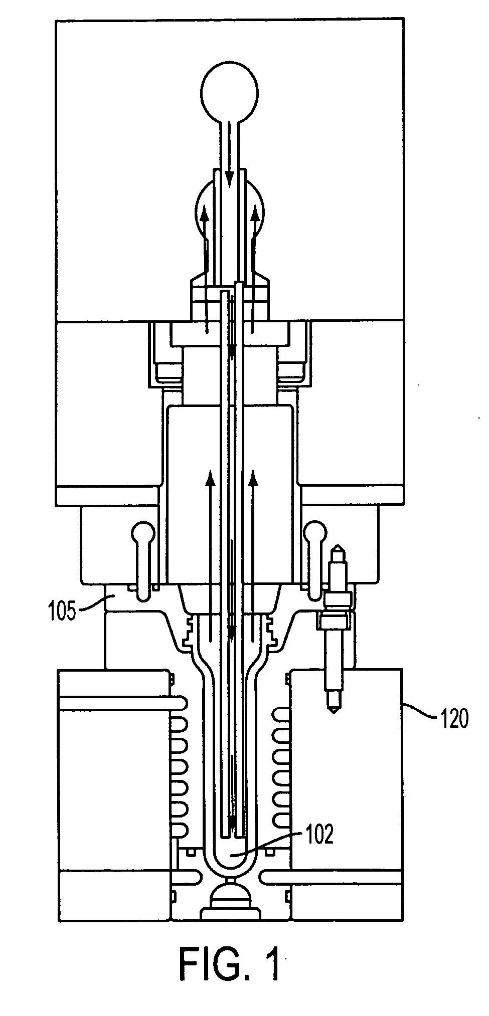
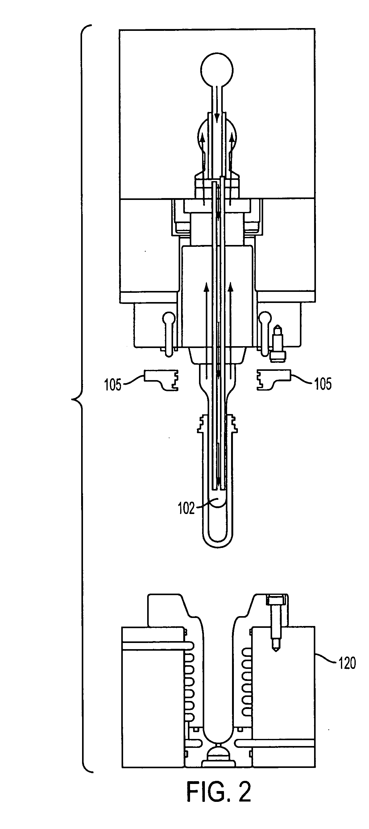
[0026]FIG. 1 illustrates an injection molding apparatus having a completely formed preform upon the core 102. Removal occurs by the cavity plate 120 sliding away and separating from the remainder ...


PUM

PropertyMeasurementUnit
thicknessaaaaaaaaaa
hardnessaaaaaaaaaa
forceaaaaaaaaaa

Abstract

A device for fracturing a defective preform for use in blowmolding is claimed. The preform has head end and a tail end and the device comprises a tube with walls defining a cavity for accepting the defective preform while the defective preform is on a core of an injection molding apparatus, an attachment element that attaches the tube to the injection molding apparatus, and locates the tube relative to the core; and a percussion instrument that contacts and breaks the defective preform at the tail end of the preform.

Description

BACKGROUND OF THE INVENTION [0001] 1. Field of the Invention [0002] The present invention relates generally to defective preforms and more particularly to removal of defective preforms from an injection molding apparatus. [0003] 2. Related Art [0004] Preforms created in the injection molding process are sometimes defective in that they cannot be easily removed from the core of the injection molding apparatus over which the preforms are shaped. One common example is when the plastic does not form the entire preform. In this instance the preform does not cover the core and cannot be removed from the core using the mold ejector plate. As a result, the defective preform must be cooled and struck at its bottom end with a hammer, such as a brass or aluminum hammer in order to crack the plastic and remove the preform from the core. [0005] Most cores are made from steel and have sufficient hardness to withstand the impact of being struck with a hammer. The benefit of an ampcoloy core is tha...

Claims


Application Information

Patent Timeline
Patent Type & Authority Applications(United States)
IPC IPC(8): B29C49/42
CPCB29B11/08B29C45/17B29K2105/253B29C49/06B29C45/40B29C49/4238B29C2949/0715
Inventor SHEETS, PHILIPDUNMAN, JAMES
Owner GRAHAM PACKAGING CO LP
Learn More