Fuel cell system

Inactive Publication Date: 2006-03-30
NISSAN MOTOR CO LTD
View PDF0 Cites 33 Cited by
  • Summary
  • Abstract
  • Description
  • Claims
  • Application Information

AI Technical Summary

Benefits of technology

[0007] The present invention has been proposed in order to solve such disadvantages inherent in the conventional fuel cell system. It is an object of the present invention to provide an on-vehicle fuel cell system that is free

Problems solved by technology

However, in the conventional technologies, external circumstances and the like are not considered in discharging the extra water to the outside.
Therefore, in the case of mo

Method used


Image

  • Fuel cell system
  • Fuel cell system
  • Fuel cell system

Examples


first embodiment

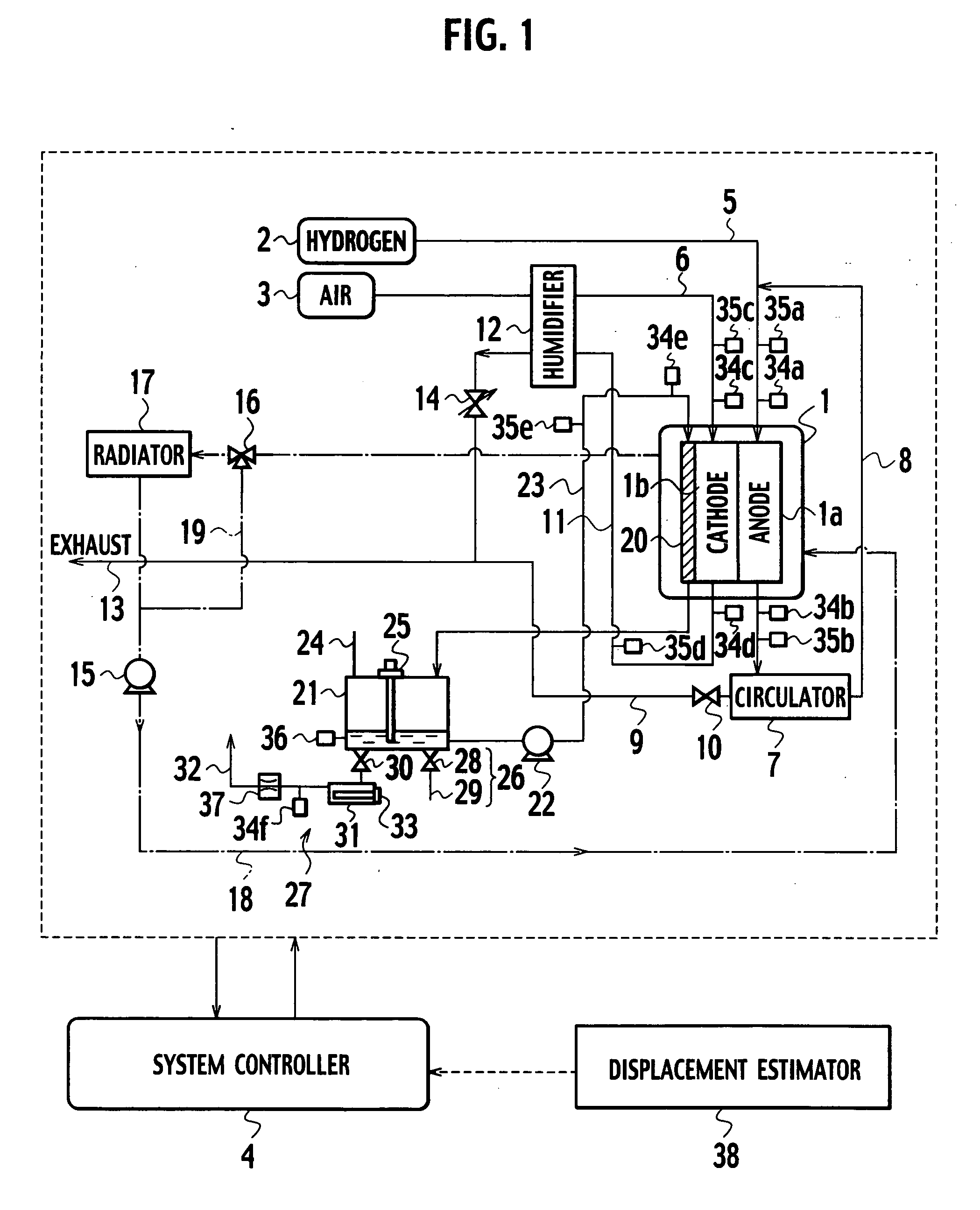
[0023]FIG. 1 shows a configuration of a fuel cell system of this embodiment. The fuel cell system of this embodiment is a system mounted on a vehicle, which serves as a drive power source of the vehicle, and uses a solid polymer-type fuel cell stack 1 as a power generation device. Moreover, in this fuel cell system, hydrogen as fuel gas is supplied from a hydrogen supply device 2 to an anode electrode 1a of the fuel cell stack 1, and in addition, air as oxidant gas is supplied from an air supply device 3 to a cathode electrode 1b of the fuel cell stack 1. Then, in the fuel cell stack 1, the supplied hydrogen and oxygen in the supplied air are reacted electrochemically with each other, and power is thus generated. Controls for various operation states in this fuel cell system are executed based on instructions from a system controller 4.

[0024] The fuel cell stack 1 is composed of single cells. Each single cell is formed in such a manner that the anode electrode 1a to which the hydro...

second embodiment

[0053] Next, a fuel cell system of a second embodiment to which the present invention is applied is described. As shown in FIG. 6 and FIG. 7, the fuel cell system of this embodiment has a feature in that a receiver 39 of a discharge prohibition signal is provided in place of the displacement estimator 38 for use in estimating the road surface condition in the above-described first embodiment. Note that other basic configurations of the system are similar to those of the above-described first embodiment.

[0054] The receiver 39 is one for receiving the discharge prohibition signal transmitted from a transmitter 41 provided in a facility 40 or the like in the outside of the vehicle. Specifically, in this embodiment, a transmitter 41 for transmitting the discharge prohibition signal to the effect that the discharge of the extra water in the state of the liquid-water is prohibited is provided in the facility 40 or the like having the space allowing the person, the article and the automob...

third embodiment

[0058] Next, a fuel cell system of a third embodiment to which the present invention is applied is described. As shown in FIG. 9, the fuel cell system of this embodiment has a feature in that a switch 42 arbitrarily switchable by a passenger on the vehicle is provided in place of the displacement estimator 38 for use in estimating the road surface condition in the above-described first embodiment. Note that other basic configurations of the system are similar to those of the above-described first embodiment.

[0059] In the fuel cell system of this embodiment, when the passenger on the vehicle has determined that the road surface condition immediately under the vehicle is a road surface condition unsuitable for the discharge of the extra water in the state of the liquid-water as a result of a confirmation of the road surface condition by viewing the same, and so on, the steam discharge device 27 can be selected as the device for discharging the extra water in the water tank 21 by swit...


PUM


Abstract

An on-vehicle fuel cell system of the present invention has: a fuel cell stack which is mounted on a vehicle and generates power by using fuel gas and oxidant gas, the fuel cell stack including a water passage which performs cooling and humidification in an inside thereof; a water circulator which circulates water through the water passage; a water tank which reserves the water; a discharge device which discharges extra water from the water tank to an outside of the vehicle; and a discharge control device which controls the discharge of the water by the discharge device. The discharge control device makes a control not to discharge liquid-water to the outside of the vehicle in a case where a road surface condition immediately under the vehicle is estimated to be a predetermined road surface condition.

Description

BACKGROUND OF THE INVENTION [0001] 1. Field of the Invention [0002] The present invention relates to a fuel cell system mounted on a vehicle, and particularly, to an improvement for appropriately discharging extra water in a system to the outside. [0003] 2. Description of the Related Art [0004] As a countermeasure against environmental problems in recent years, in particular, against such problems as air pollution caused by exhaust gas of automobiles and the like and global warming caused by carbon dioxide, a fuel cell system enabling clean exhaust and high energy efficiency has attracted attention. The fuel cell system is an energy conversion system that causes an electrochemical reaction by supplying air and hydrogen serving as fuel to a hydrogen electrode and an air electrode in a fuel cell stack, and converts chemical energy into electrical energy. In the fuel cell system, it is only water that is generated by the electrochemical reaction, and exhaust gas containing a toxic subs...

Claims


Application Information

Patent Timeline
IPC IPC(8): H01M8/00
CPCH01M8/04029Y02E60/50H01M8/04134H01M8/04156H01M8/04291H01M8/04313H01M8/04328H01M8/04335H01M8/04343H01M8/0435H01M8/04358H01M8/04388H01M8/04395H01M8/04402H01M8/0441H01M8/04746H01M8/04828H01M2250/20Y02T90/32H01M8/04037Y02T90/40
Inventor MATOBA, TADASHI
Owner NISSAN MOTOR CO LTD
Why Eureka
Try Eureka