Fastener apparatus for tissue and methods of deployment and manufacture

a technology of fastener apparatus and tissue, which is applied in the field of fastener apparatus for tissue and methods of deployment and manufacture, can solve the problems of affecting the patient's recovery, requiring a long time to complete the procedure, and he or she is more likely to experience complications, etc., and achieves the effects of quick and reliable, convenient and fast penetration of tissue, and simple design

Active Publication Date: 2006-03-30
WRIGHT DAVID W
View PDF24 Cites 26 Cited by
  • Summary
  • Abstract
  • Description
  • Claims
  • Application Information

AI Technical Summary

Benefits of technology

[0012] An object, feature or advantage of this invention, in one or more embodiments of the invention, is to provide an apparatus and method of deployment that provides a secure and reliable side anastomosis between a tubular duct and a wall of a vessel.
[0013] Another object, feature or advantage of this invention, in one or more embodiments of the invention, is to provide an apparatus and method of deployment that establishes a quick biocompatible bond between mating tissues.
[0014] Another object, feature or advantage of this invention, in one or more embodiments of the invention, is to provide an apparatus and method of deployment that imparts a biasing force to maintain connected tissues in abutting contact with one another.
[0015] Another object, feature or advantage of this invention, in one or more embodiments of the invention, is to provide an apparatus and method of deployment that readily penetrates tissue without damaging the tissue.
[0016] Another object, feature or advantage of this invention, in one or more embodiments of the invention, is to provide an apparatus and method of deployment that provides a quick and reliable mechanism in which to attach separate tissues to one another.
[0017] Another object, feature or advantage of this invention, in one or more embodiments of the invention, is to provide an apparatus and method of deployment that is of relatively simple design and is economical in manufacture and assembly and is efficient in use.

Problems solved by technology

The entire procedure is ordinarily quite exhausting and requires a long time to complete the procedure, generally ranging between 2 to 6 hours or more.
The longer the patient is on the bypass system, the more likely he or she is to experience such complications.
Though using sutures to join segments of tissue to one another in open heart surgery, or other forms of surgery, has proven successful, not only does it require a longer than desirable amount of time in surgery, there is also a danger of the suture becoming damaged.
Damage to a portion of the suture may occur in many ways, such as through inadvertent grasping or clamping by a surgical instrument or through nicking a suture with the needle as an adjacent suture is installed.
Ordinarily, a damaged piece of suture has a substantially reduced tensile strength and thus may ultimately fail to maintain the pieces of tissue joined to one another.

Method used


Image

  • Fastener apparatus for tissue and methods of deployment and manufacture
  • Fastener apparatus for tissue and methods of deployment and manufacture
  • Fastener apparatus for tissue and methods of deployment and manufacture

Examples


Embodiment Construction

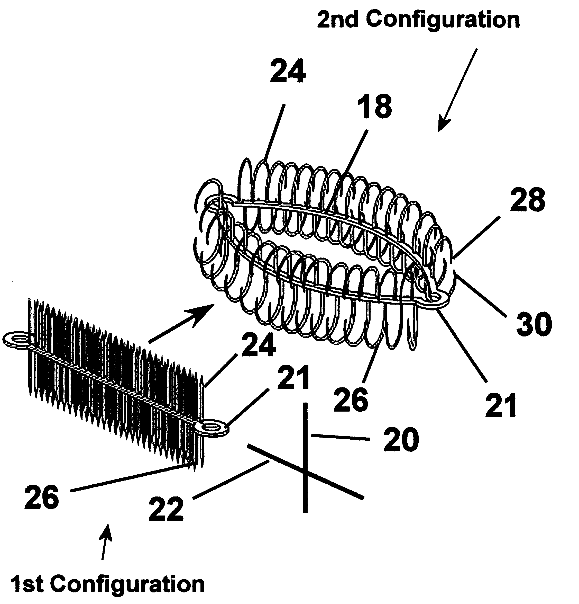
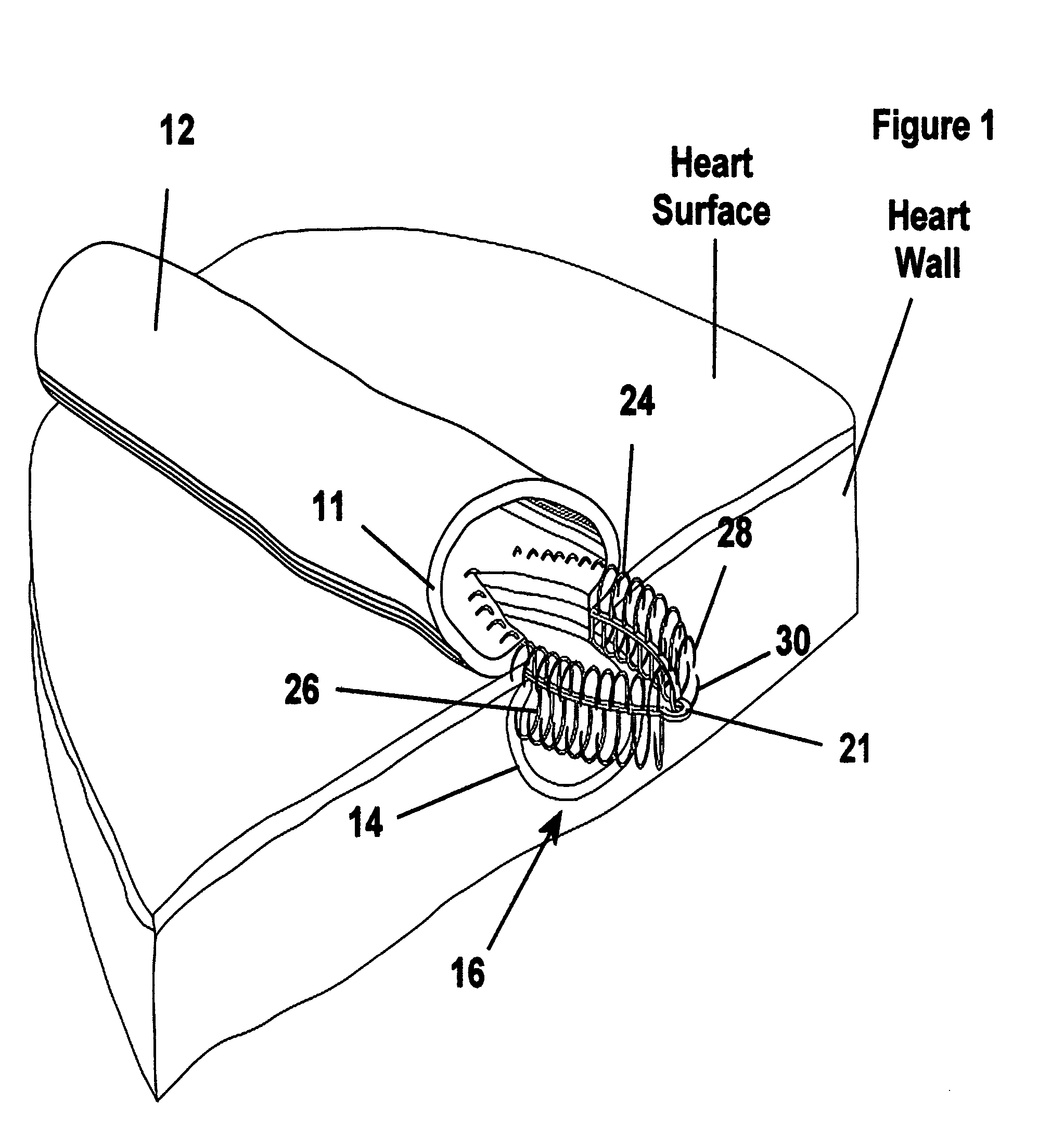
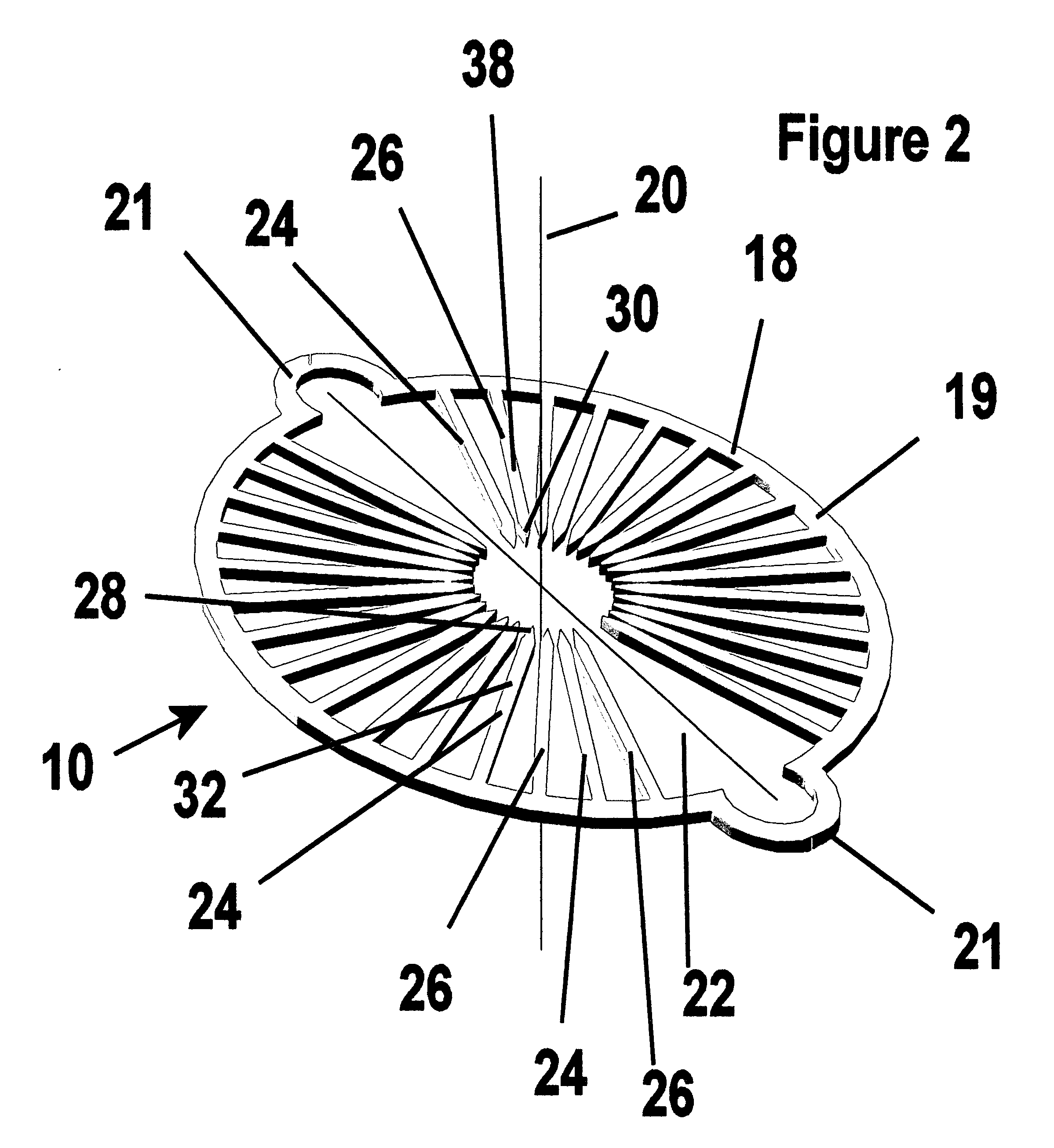
[0056] Referring to FIG. 1, an apparatus, referred to hereafter as a fastener 10, is shown making a generally tangential anastomosis between two pieces of tissue, represented here as a wall 11 of a generally tubular duct 12, for example and without limitation, a graft of an artery or vein, and a wall 14 of a vessel 16, for example and without limitation, a wall forming a coronary artery. The anastomosis established by the fastener 10 provides a sutureless connection between a wall 11 of the tubular duct 12 and the wall 14 of a vessel 16, thereby facilitating making a tangential connection between the duct 12 and the vessel 16. Desirably, the fastener 10 biases the tubular duct 12 and the wall 14 of the vessel 16 toward one another, thereby establishing a leakproof attachment between the tubular duct 12 and the vessel 16. Additionally, the continual bias imparted by the fastener 10 between the tubular duct 12 and the wall 14 of the vessel 16 facilitates the formation of a biological ...


PUM


Abstract

A device for connecting two tubular vessels together in a side-by-side or tangential manner is disclosed. The device has an annulus and at least one series of fingers connected to and extending away from the annulus. In the preferred embodiment there are two sets of fingers connected to and extending away from the annulus in opposite directions. Each finger is preferably biased into an arcuate shape. In use, a deployment apparatus is used to constrain the fingers of the device to be in a relatively planar configuration. The deployment apparatus containing the device is placed between and in contact with the two tubular vessels so that one tubular vessel is above the device and one tubular vessel is below the device and so that the fingers of the device come into contact with the tissue of the vessels. As the fingers penetrate the vessels the constraint on the fingers is removed so that the fingers can assume their biased arcuate shape. In this way, the fingers penetrate and grasp the tissue of the vessels so that the device grasps the vessels and pulls the vessels toward each other.

Description

CROSS REFERENCE TO RELATED APPLICATION [0001] This application claims the benefit of, and incorporates in by reference in its entirety, U.S. Provisional Application Serial No. 60 / 613,434 filed Sep. 27, 2004.BACKGROUND OF THE INVENTION [0002] 1. Field of the Invention [0003] This invention relates generally to methods and devices for surgically joining separate pieces of tissue to one another, and more particularly to surgically joining a tubular graft of tissue to a separate piece of tissue. [0004] 2. Related Art [0005] In performing bypass surgery, it is a known practice to repair a clogged or an otherwise damaged segment of tubular tissue, for example a coronary artery, by attaching a healthy section of artery, for example, a mammary artery, to the tubular tissue below the clog or damaged segment so that blood flows from the healthy section of artery into the tubular tissue below the clogged or damaged segment. In addition, it is also known to bypass a clogged or damaged section o...

Claims


Application Information

Patent Timeline
Patent Type & Authority Applications(United States)
IPC IPC(8): A61B17/08
CPCA61B17/072A61B17/11A61B2017/1139A61B2017/00243A61B2017/1107A61B17/115A61B17/122A61B17/128
Inventor WRIGHT, DAVID W.
Owner WRIGHT DAVID W
Why Eureka
Try Eureka