Rotary cutter drum and a rotary cutter unit with such a rotary cutter drum

a rotary cutter and rotary cutter technology, which is applied in the direction of metal-working equipment, shearing equipment, metal-working equipment, etc., can solve the problems of longer life time and longer edge life, and achieve the effect of fast and easy manner

Inactive Publication Date: 2006-04-06
SANDVIK INTELLECTUAL PROPERTY AB
View PDF20 Cites 1 Cited by
  • Summary
  • Abstract
  • Description
  • Claims
  • Application Information

AI Technical Summary

Benefits of technology

[0016] Hereby is achieved that the inserts Ja, Jb of FIGS. 5 and 6 can be eliminated. Furthermore, less machining of the knife member is required.
[0017] Suitably, the outer periphery of the knife member comprises a pair of cutting edges and a slanting portion extending from each edge towards said surfaces, respectively, said slanting portion extending to at least 50% of the radial extension of said knife member. Alternatively, the slanting portion extends substantially the whole radial extension of said knife member. Hereby is achieved that grinding can be performed in a faster and easier manner; sharp corners are avoided. Furthermore, a longer life time of the edge is achieved and thus also a longer life time thereof.
[0019] Preferably, a plurality of openings are formed in the cutter portion adapted to be associated with a source of gas having a controllable pressure, at least one opening being arranged substantially at said knife member. Hereby, it is possible to provide the surface with more holes than previously possible, and a wider possibility of achieving a desired hole distribution, such that a more efficient connection of the web and a more efficient release of the cut article and / or the waste trim from the surface can be achieved. Furthermore, leakage occurring in the prior art between the surface and a steel insert is eliminated.

Problems solved by technology

Furthermore, a longer life time of the edge is achieved and thus also a longer life time thereof.

Method used


Image

  • Rotary cutter drum and a rotary cutter unit with such a rotary cutter drum
  • Rotary cutter drum and a rotary cutter unit with such a rotary cutter drum
  • Rotary cutter drum and a rotary cutter unit with such a rotary cutter drum

Examples


Embodiment Construction

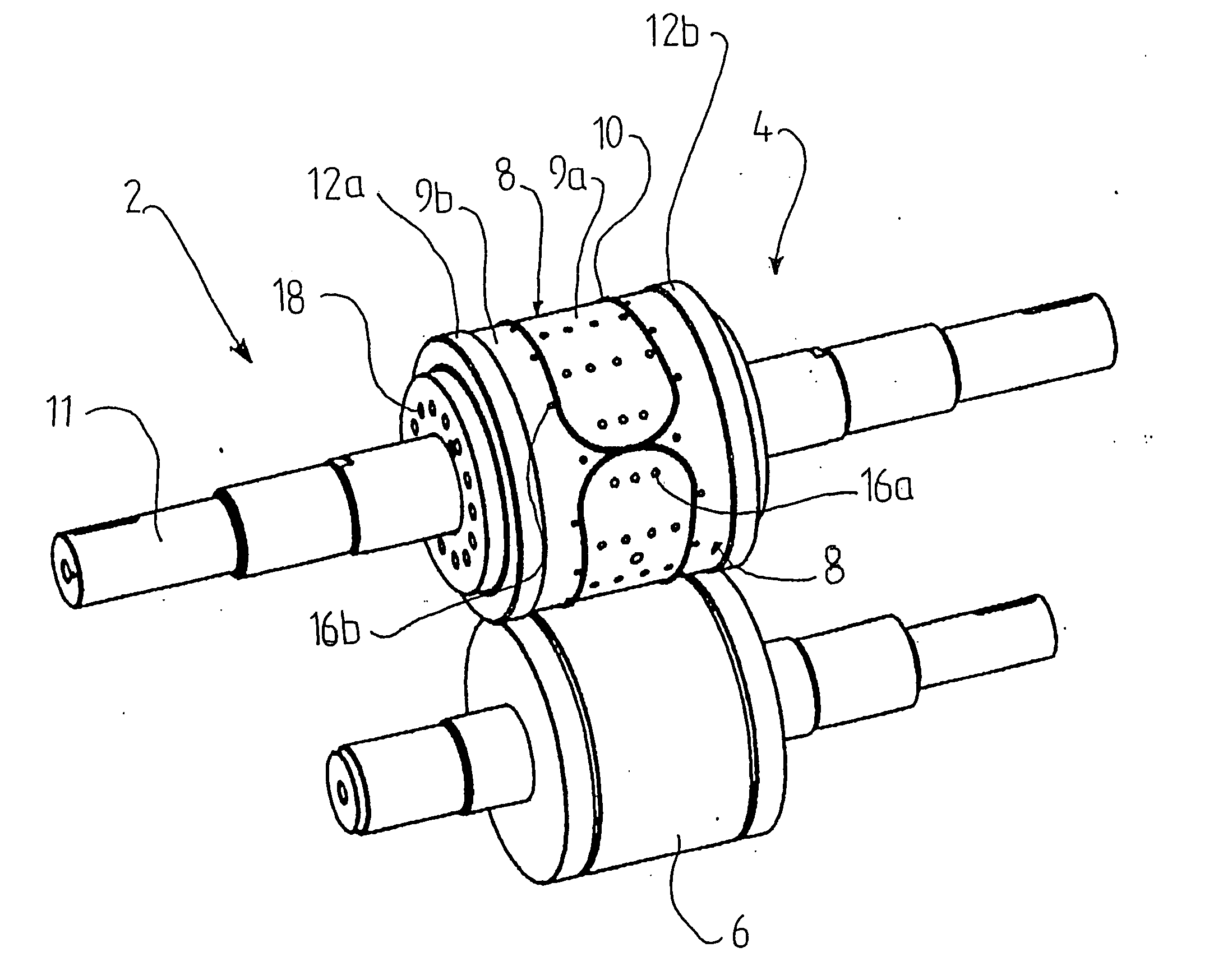
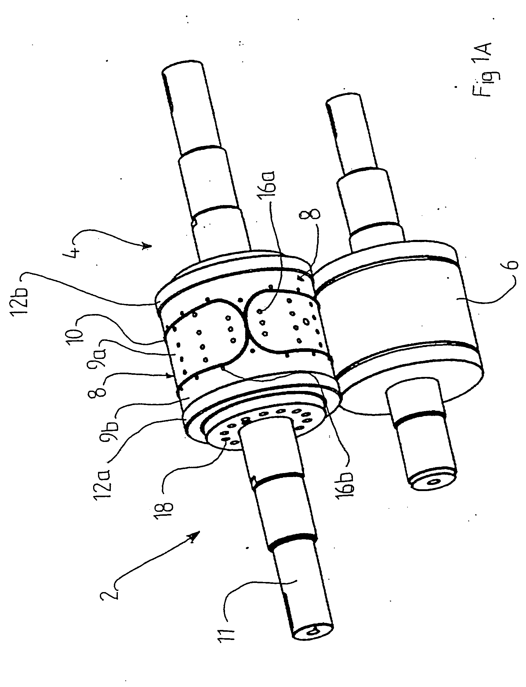
[0037]FIG. 1A shows a rotary cutter unit 2 comprising a rotary cutter drum 4 made of a multiphase material, such as a carbide, ceramics or metallic powder, arranged in working relationship with a rotary anvil drum 6.

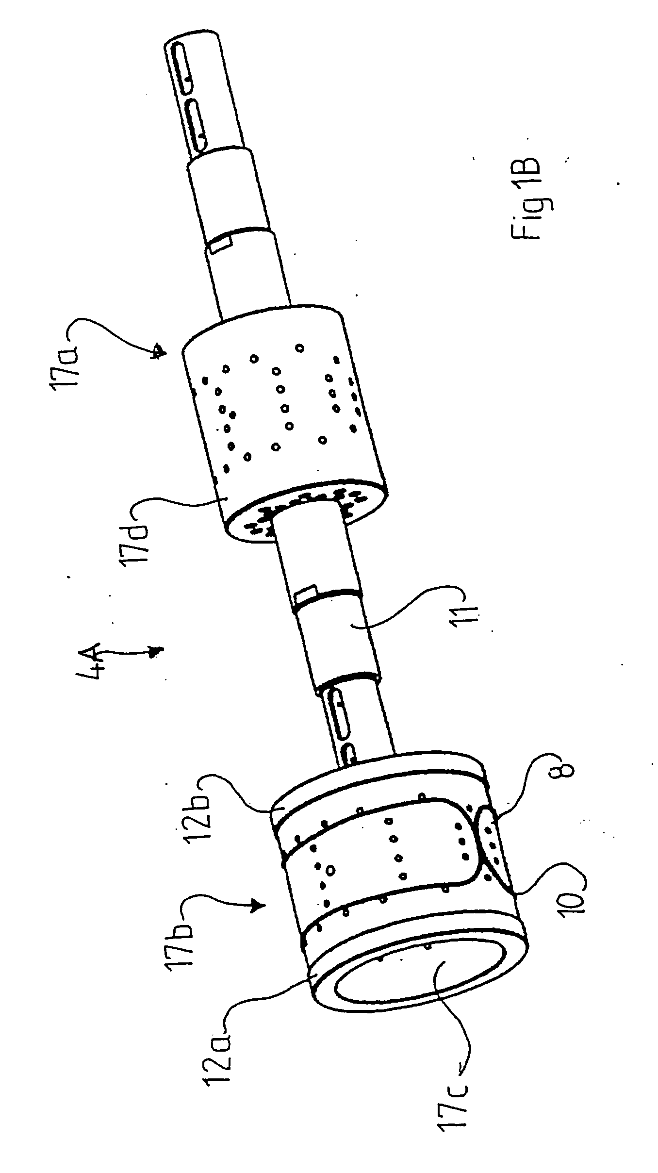
[0038] The drum 4 is generally solid and has a pair of annular abutment members 12a, 12b, produced in one piece of a multiphase material, such as a carbide or ceramics. The rotary cutter drum 4 is provided with a cutter portion 8 situated axially between the abutment members 12a, 12b. The cutter portion has outwardly exposed surfaces 9a, 9b on either side of at least one endless knife member 10 of the cutter portion, which knife member protrudes radially outwardly beyond said surfaces 9a, 9b. The radially outer periphery of the knife member 10 has a diameter larger than that of each of said surfaces 9a, 9b.

[0039] The knife member 10 extends 6-14 mm from the surface 9a and forms a cutting edge structure at its radially outer periphery. The rotary cutter drum 4 is provid...


PUM

PropertyMeasurementUnit
diameteraaaaaaaaaa
thicknessaaaaaaaaaa
diametersaaaaaaaaaa

Abstract

A rotary cutter drum includes a cutter portion formed of a multiphase material and includes first and second substantially cylindrical, radially outwardly exposed surfaces, and a knife member formed of one piece with the exposed surfaces and arranged to axially separate the first and second surfaces from one another. The knife member protrudes by a distance in the range of 1 to 5 mm radially outwardly beyond a smallest diameter portion of the first and second exposed surfaces. The knife member includes two sides terminating at respective ones of the first and second exposed surfaces.

Description

[0001] The present application claims priority under 35 U.S.C. §119 to Patent Application Serial No. 0401734-9 filed in Sweden on Jul. 2, 2004. TECHNICAL BACKGROUND OF THE INVENTION [0002] The present invention relates to a rotary cutting device for a rotary cutting apparatus, comprising at least one part made of a multiphase material, including at least one cutter portion having a first and a second substantially circular cylindrical outer surface, said cutter portion comprising at least one knife member protruding from and separating said first and second surfaces from each other, said first and second surfaces and said knife member being integral parts of said cutter portion. [0003] The invention also relates to a rotary cutting apparatus comprising an anvil roll and such a rotary cutter. [0004] Such a rotary cutter and such a rotary cutting unit marketed by Sandvik AB under the trade name “Sandvik CRC” (i.e. “carbide rotary cutter”) are illustrated in FIGS. 5 and 6. The known ro...

Claims


Application Information

Patent Timeline
Patent Type & Authority Applications(United States)
IPC IPC(8): B26D1/22B26D1/62B26D7/26B26F1/38
CPCB26D1/626B26F1/384B26D7/265B26D7/2614Y10T83/9312Y10T83/4838Y10T83/9377Y10T83/9457Y10T83/7851Y10T83/4795Y10T83/483Y10T83/9464B26D7/26B26F1/38B26D1/40B26F1/44
Inventor GRENIER, GILBERTBATY, STEPHANIE
Owner SANDVIK INTELLECTUAL PROPERTY AB
Why Eureka
Try Eureka