Surgical tool system with integrated pump

a surgical tool and integrated technology, applied in the direction of electric generator control, dynamo-electric converter control, dynamo-electric gear control, etc., can solve the problems of increasing the time it takes to perform a surgical procedure, data type cannot guarantee the proper type of tube set, and confusion during a surgical procedur

Active Publication Date: 2006-04-06
STRYKER CORP
View PDF11 Cites 68 Cited by
  • Summary
  • Abstract
  • Description
  • Claims
  • Application Information

AI Technical Summary

Benefits of technology

[0011] Still another feature of this invention is that the control console processor, based on the read data, is able to prime the pump. That is, the control console actuates the pump for a fixed amount of time to cause the head of the fluid in the tube set to be forced relatively close to the distal end discharge opening.

Problems solved by technology

The availability of these different surgical tools and pump tube sets can potentially lead to confusion during a surgical procedure.
Taking the time to double check to ensure that the proper tube set is attached to a pump and / or having to quickly change the tube set if the oversight is not discovered, can increase the time it takes to perform a surgical procedure.
Even providing this type of data cannot guarantee that the proper type of tube set will be installed in pump for a given surgical procedure.
Still another problem with currently available pumps concerns their priming.
If the pump is not primed, when the pump is initially actuated, there is a delay until the fluid is forced through the tube set and discharged.
Requiring surgical personnel to perform this task takes time and, in some situations, may take more time then simply waiting for the fluid to be discharged from an unprimed tube set.
Moreover, it may be difficult for surgical personnel to accurately prime the tube set by turning the pump on and off.
If the pump is turned on for too short a time, the tube set may be insufficiently primed.
This discharge just needlessly adds to the presence of undesirable liquid-state waste material in the operating room.

Method used


Image

  • Surgical tool system with integrated pump
  • Surgical tool system with integrated pump
  • Surgical tool system with integrated pump

Examples


Embodiment Construction

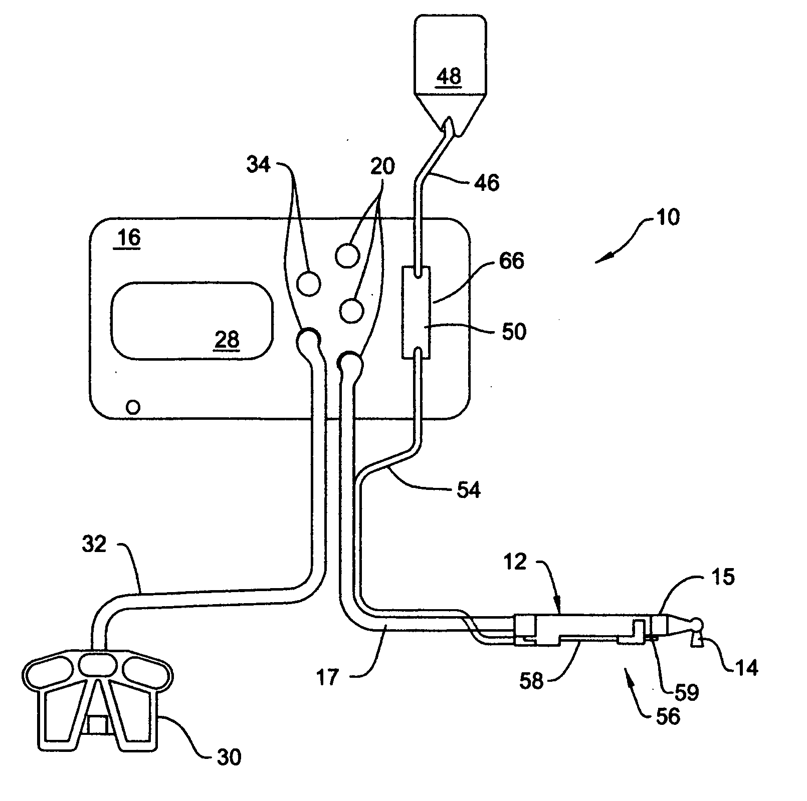
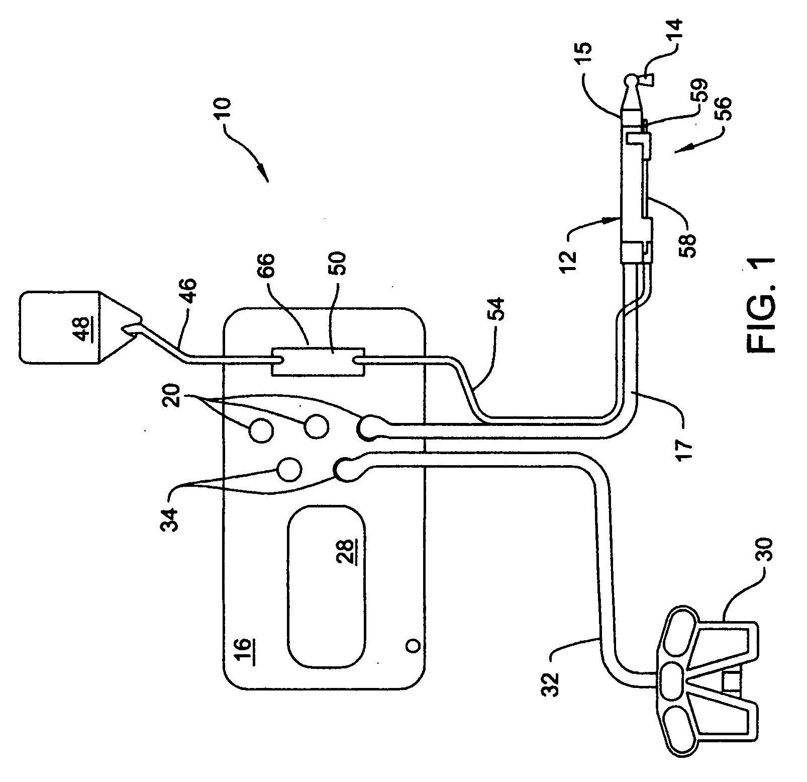
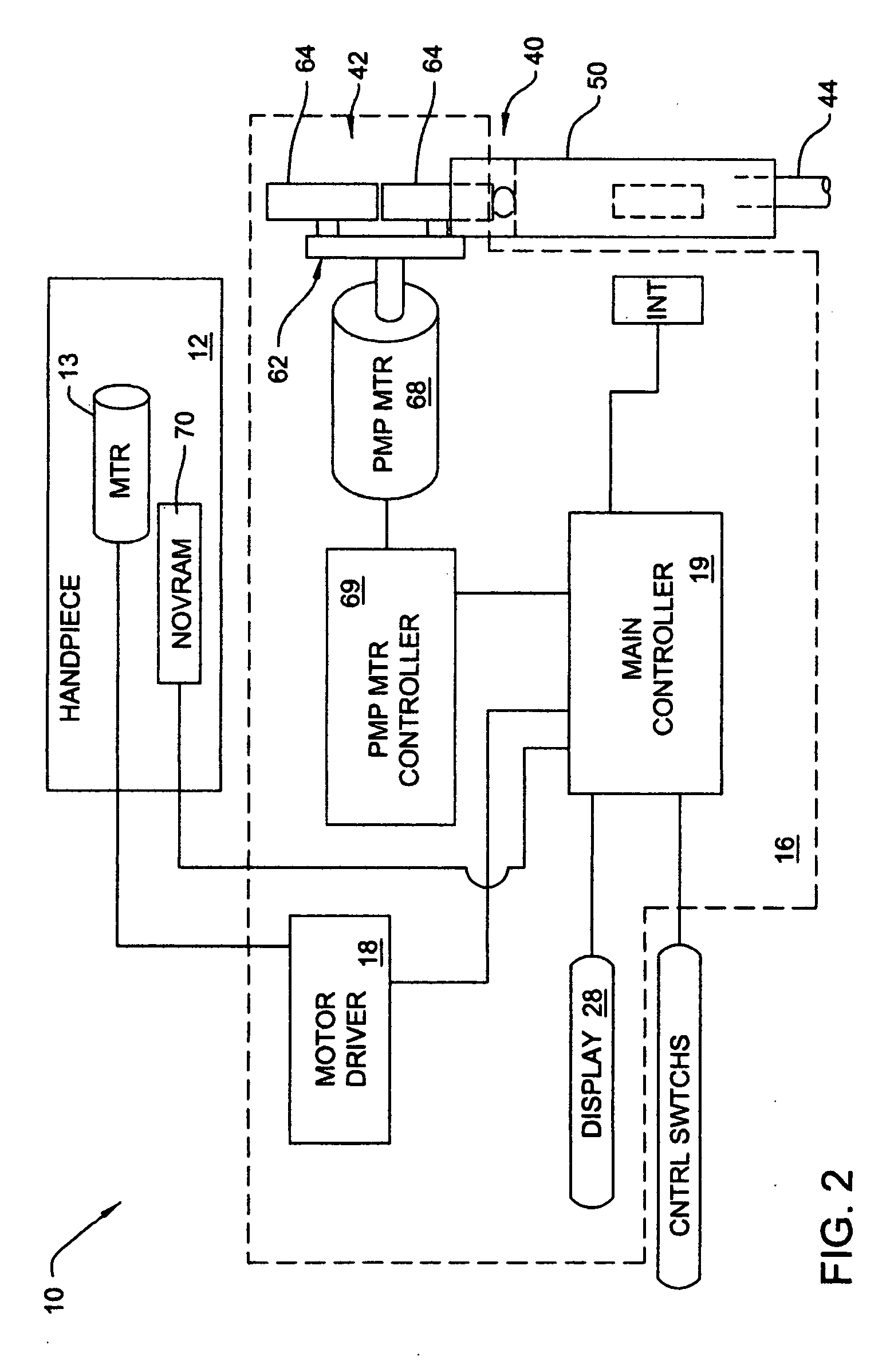
[0027]FIGS. 1 and 2 illustrate the basic features of a surgical tool system 10 of this invention. System 10 includes a powered handpiece 12 used to perform a surgical procedure on a patient. The illustrated handpiece 12 is a saw. Internal to the handpiece 12 are a motor 13 and a gear assembly (gear assembly not illustrated). In the illustrated handpiece 12, motor 13 and the gear assembly oscillate a blade 14 removably attached to the distal end of the handpiece 12. (“Distal,” it should be understood, means away from the surgeon / towards the patient. “Proximal” it should be understood, means towards the surgeon / away from the patient.) Other handpieces may be provided with other and motor gear assemblies to drive the associated cutting accessories in rotational movement. Blade 14 and other cutting accessories are removably connected to the handpiece 12 and motor 13 by a coupling assembly 15 integral with the handpiece.

[0028] The handpiece 12 is removably attached to a control console ...


PUM


Abstract

A tool system for both powering a handpiece and operating an irrigation pump. The pump includes a fixed pump head driven by a pump motor and a removable tube set. A readable memory such as RFID is integral with the tube set. The tube set memory contains data describing the physical characteristics of the tube set. A control console reads the data in the tube set memory. Based on these data, data from the handpiece and the characteristics of the motor driving the pump head, the control console determines if the pump, including the tube set can provide irrigation fluid at appropriate flow rates for the handpiece. If the assembled pump, specifically the pump head and tube set, can provide fluid at the appropriate flow rates, the control console then regulates the operation of the pump motor so that fluid, when required, is delivered at those flow rates.

Description

FIELD OF THE INVENTION [0001] This invention relates generally to a powered surgical tool system with a pump. More particularly, this invention relates to a powered surgical tool system wherein the operation of the pump is integrated with the operation of the surgical handpiece with which the pump is used. BACKGROUND OF THE INVENTION [0002] In modern surgery, one or more surgical sub-procedures are performed with powered surgical handpieces. A handpiece may include a motor that drives a cutting accessory such as a drill bit, saw blade or a bur. Alternatively, the handpiece may be an electrocautery device, or a tissue ablation tool that removes and / or shapes the tissue with RF energy, ultrasonic energy or light energy. The electrical energy used to actuate these handpieces often comes from a control console to which the handpiece is connected. [0003] During the performance of many surgical procedures, it is often desirable to apply an irrigation fluid to the site at which the procedu...

Claims


Application Information

Patent Timeline
Patent Type & Authority Applications(United States)
IPC IPC(8): F04B43/08F04B43/12
CPCA61B17/1626A61B2017/00017A61B2017/00464A61B2017/00482A61B2019/448A61B2217/005A61B2217/007A61M3/0258A61M2205/3331A61M2205/3523A61M2205/3569A61M2205/6018A61B90/98A61M3/022A61M3/0208A61M2205/12A61M2205/60A61M2205/52A61M2205/3592A61M3/0201A61M3/0202
Inventor MALACKOWSKI, DON
Owner STRYKER CORP
Why Eureka
Try Eureka