
Anion generator

a generator and anion technology, applied in the field of electric power generation, can solve the problems of high cost, high failure rate, breakdown between turns and short circuits, etc., and achieve the effects of low cost, no short circuit protection, and high boost ratio

Inactive Publication Date: 2006-04-06
XIAN H LEADER NEGATIVE ION TECH
View PDF10 Cites 14 Cited by
  • Summary
  • Abstract
  • Description
  • Claims
  • Application Information

AI Technical Summary

Benefits of technology

[0007] In view of foregoing reasons, the objective of the invention is to provide an efficient, diffusible anion generator which has small volume, no short-circuit protection, high boosting ratio, simple insulation construction, safe and stabilized, low electromagnetic interference.
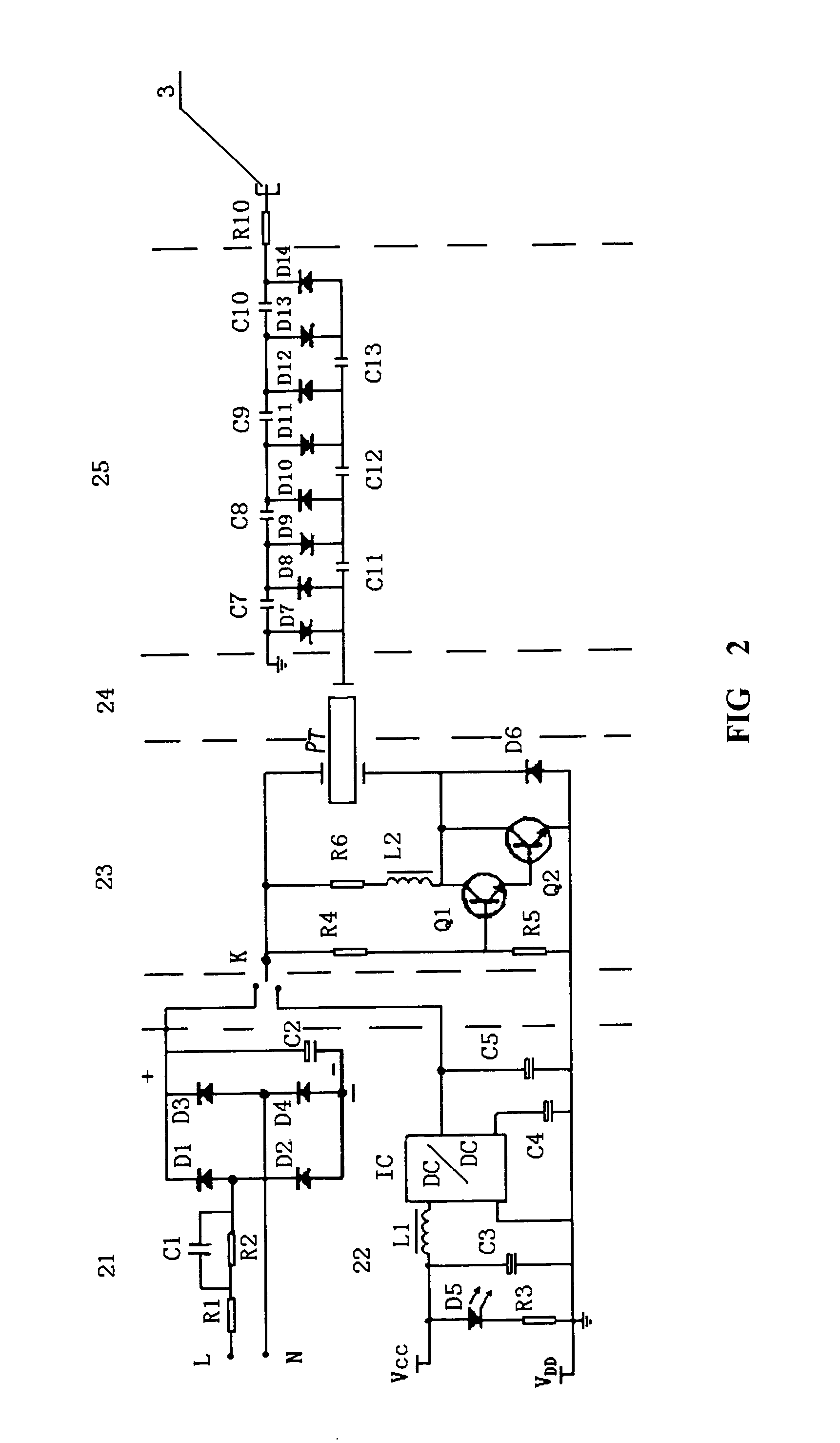
[0017] Said oscillation circuit is mainly composed of resistances, composite triodes and inductors; as the loop capacitance of the oscillation circuit, the input capacitance of the sheet piezoelectric ceramic transformer of said boosting circuit is connected between the base electrode and collecting electrode of composite triode, so that the oscillation circuit with sheet piezoelectric ceramic transformer can form self-oscillation.
[0019] Viewing from above description, the invention has following advantages:
[0020] 1. As certain electric potential is applied to the conducting protective grille, an electric field is formed on the casing of anion generators. The electric field accelerates the escape velocity of anions, while the discharge resistance releases a few anion absorbed by the protective grille in time, to make the grille maintaining at a certain potential, so that the anion can efficiently escape into air and its density at 30 cm away from the grille is more than 3×10⁶ / cm3, and this not only purifies air but also performs disinfection, thus solving the problem, i.e. the existing anion generator is ineffective when ion escapes away from the casing, greatly improving the availability of the ion generator.
[0021] 2. As the interior circuit uses sheet piezoelectric ceramic transformer to generate high voltage, differing from conventional wound transformer, the invention is high boosting ratio, small in volume, simple in insulation, safe and stabilized, and low electromagnetic interference.

Problems solved by technology

The interior circuit of a conventional anion generator generates a high-tension electric-field by means of a conventional wound transformer, and this claims the wound transformer to have very high boosting ratio, while the dielectric strength of primary and secondary winding of the transformer and that between turns of secondary winding to be very high, so that its process technology is complex, its cost is high and its failure rate is rising, resulting in breakdown between turns and short-circuit, even burning and other catastrophic results.
This results in the casing of anion generator acts only as a protection for interior circuit while the high density anion within the casing can escape out to outside only through diffusion or fanning by means of an electric fan, most of anion is dampened through separation or absorption of the casing so that the practical employment effect is bad.
The electric field accelerates the escape velocity of anions, while the discharge resistance releases a few anion absorbed by the protective grille in time, to make the grille maintaining at a certain potential, so that the anion can efficiently escape into air and its density at 30 cm away from the grille is more than 3×10⁶ / cm3, and this not only purifies air but also performs disinfection, thus solving the problem, i.e. the existing anion generator is ineffective when ion escapes away from the casing, greatly improving the availability of the ion generator.

Method used


Image

  • Anion generator
  • Anion generator
  • Anion generator

Examples


Embodiment Construction

[0026] To further understand the invention, the invention will be described in particular with the drawings as follows:

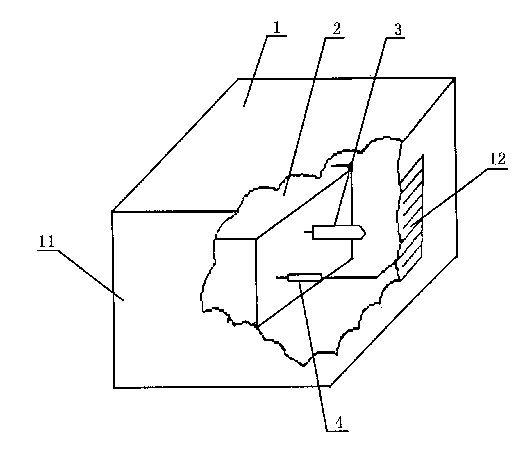
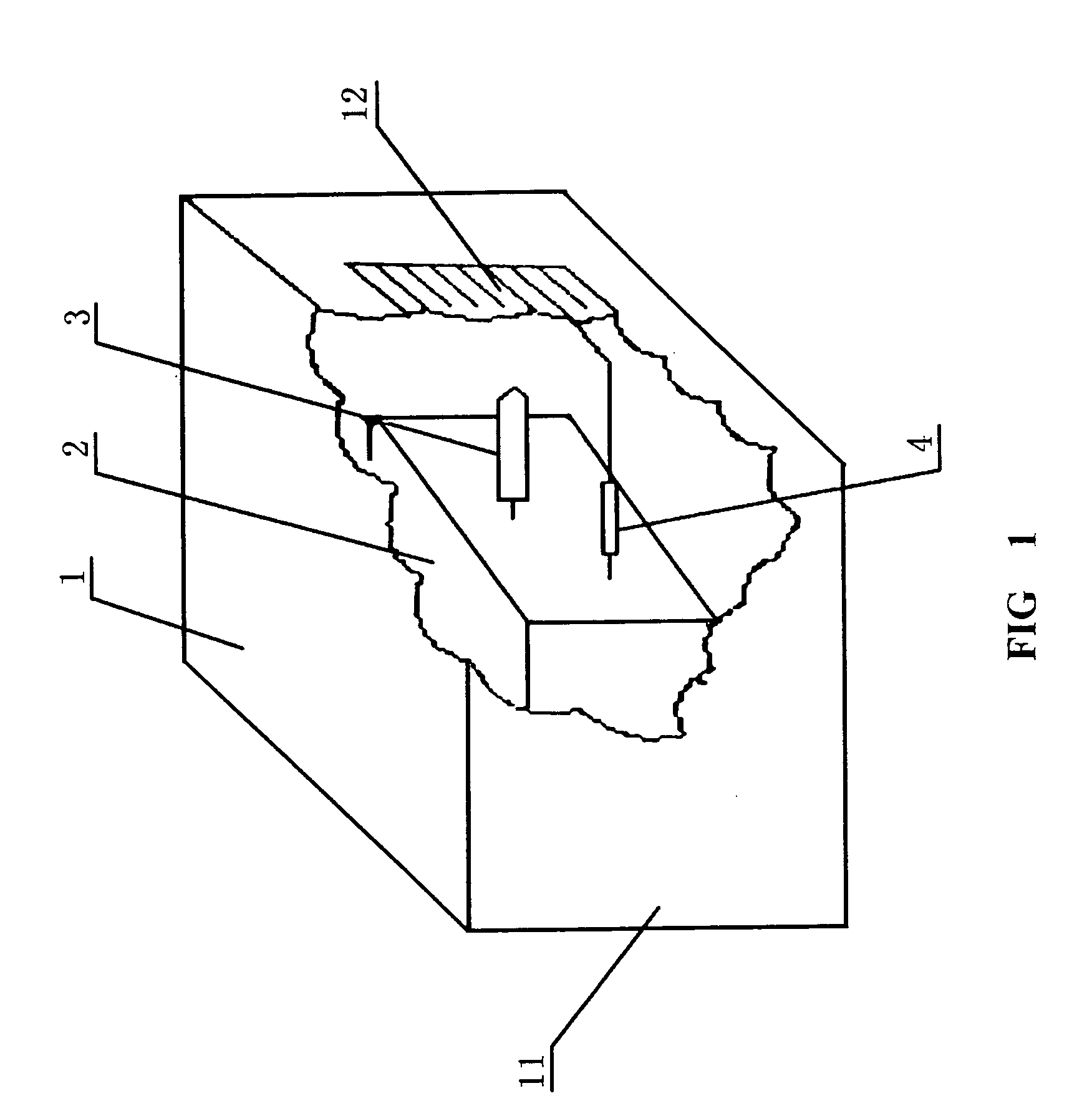
[0027] As shown in FIG. 1, an efficient and diffusible anion generator according to the invention comprises a casing 1, interior circuit 2, ion emitting head 3, discharge resistance 4,etc.

[0028] The casing 1 is composed of insulating case 11 and conducting protective grille 12 embedded in the case 11. A certain voltage is applied to the conducting protective grille 12 to form an electric field on the casing 1, the object of which is to accelerate the escape of ions produced in the anion generator. The conducting protective grille 12 is made of conducting metallic materials or semi-conducting materials, or some non-metallic materials which is treated by special process so as to have a certain conductivity. The conducting protective grille 12 can be formed as a separate component, or integrality with other part of the casing 1.

[0029] As shown in FIG. 2, the interio...


PUM


Abstract

The anion generator of the present invention is mainly composed of casing, interior circuit, ion emitting head etc. The casing comprise insulating case and conducting protective grille, the interior circuit mainly comprise power circuit and oscillation boosting circuit. The power circuit is comprised of AC power supply circuit and DC power supply circuit, which supply power for the oscillation boosting circuit alternately through change-over switch. The oscillation boosting circuit is composed of oscillation circuit, boosting circuit and multilevel dual voltage circuit. The character of the present invention is that, the conducting protective grille fixed on the casing has charge, so the diffusion of anion is accelerated; the said boosting circuit employs sheet piezoelectric ceramic transformer for boosting, which is simple in structure, small in volume and without protective circuit; and protective resistance is connected between the multilevel dual voltage circuit and ion emitting head. The circuit, casing and conducting protective grille of the invention is novel , so it's small and no protective circuit, high boosting ratio, safe and stabilized, low electromagnetic interference, fireretardant. The present invention could be used for the production of air-conditioner, vehicular and household electric appliances, beautification and health protection etc.

Description

BACKGROUND [0001] 1. Field of the Invention [0002] The present invention relates to anion generator. More particularly, the present invention relates to an efficient and diffusible anion generator, which is comprised of a sheet piezoelectric ceramic transformer to generate high voltage, a multilevel dual voltage circuit to further increase the high voltage, and an anion emitting head connected therewith to generate high-tension electric-field in order to ionize air, thus producing a great deal of anion, which will be quickly, efficiently diffused out when it is passing through a casing with conducting protective grille. The field of the invention belongs to the electronic technology field. [0003] 2. Description of Related Art [0004] It is well known that anion generators can purify environment, produce fresh air, and are of benefit to human's health and can treat some diseases taking as an auxiliary means. [0005] At present, conventional anion generator is composed of a casing, a in...

Claims


Application Information

Patent Timeline
Patent Type & Authority Applications(United States)
IPC IPC(8): B01J19/08B01J19/12H01T23/00H05C3/00
CPCH01T23/00
Inventor CHEN, YAOGANGHOU, ZHIJUN
Owner XIAN H LEADER NEGATIVE ION TECH
Learn More