Method and system for detecting a vehicle rollover

a vehicle rollover and vehicle detection technology, applied in the direction of pedestrian/occupant safety arrangement, cycle equipment, instruments, etc., can solve the problems of inability to determine inability to use the ars signal for a long time, and inability to reliably detect the inclination of the car, etc., to achieve exceptional rollover detection performance, avoid false triggering, and accurate calculation of the car roll angle

Active Publication Date: 2006-04-06
APTIV TECH LTD
View PDF7 Cites 11 Cited by
  • Summary
  • Abstract
  • Description
  • Claims
  • Application Information

AI Technical Summary

Benefits of technology

[0016] The method and system of the present invention guarantee accurate calculation of car roll angle during all recognizable driving conditions. As initial roll angle error calculated by the algorithm (before the rollover event occurrence) is vital for accurate prediction and detection of rollover event, the invented method results in exceptional rollover detection performance and enables to avoid false triggering.
[0017] The method and system of the invention is efficient and inexpensive. It requires only two sensors i.e. ARS and YLG; the rest of the signals, which are usually available in each modern vehicle are retrieved from the communication bus thereof.
[0018] By introducing the vehicle state or driving scenario parameter, the absolute angle error of the algorithm operation can be greatly reduced, as the algorithm features some sort of an “artificial intelligence”.

Problems solved by technology

As the ARS sensor signal always contains some errors (e.g. sensor drift, noise, etc.), these errors are accumulated during the integration process.
As a result, the long term integration of ARS signal, without additional corrective mechanisms, can not be relied upon in determining the car inclination.
Nevertheless even in the case of using two independent accelerometers, during specific driving scenarios the averaged accelerometer based angle may contain errors.

Method used


Image

  • Method and system for detecting a vehicle rollover
  • Method and system for detecting a vehicle rollover
  • Method and system for detecting a vehicle rollover

Examples


Embodiment Construction

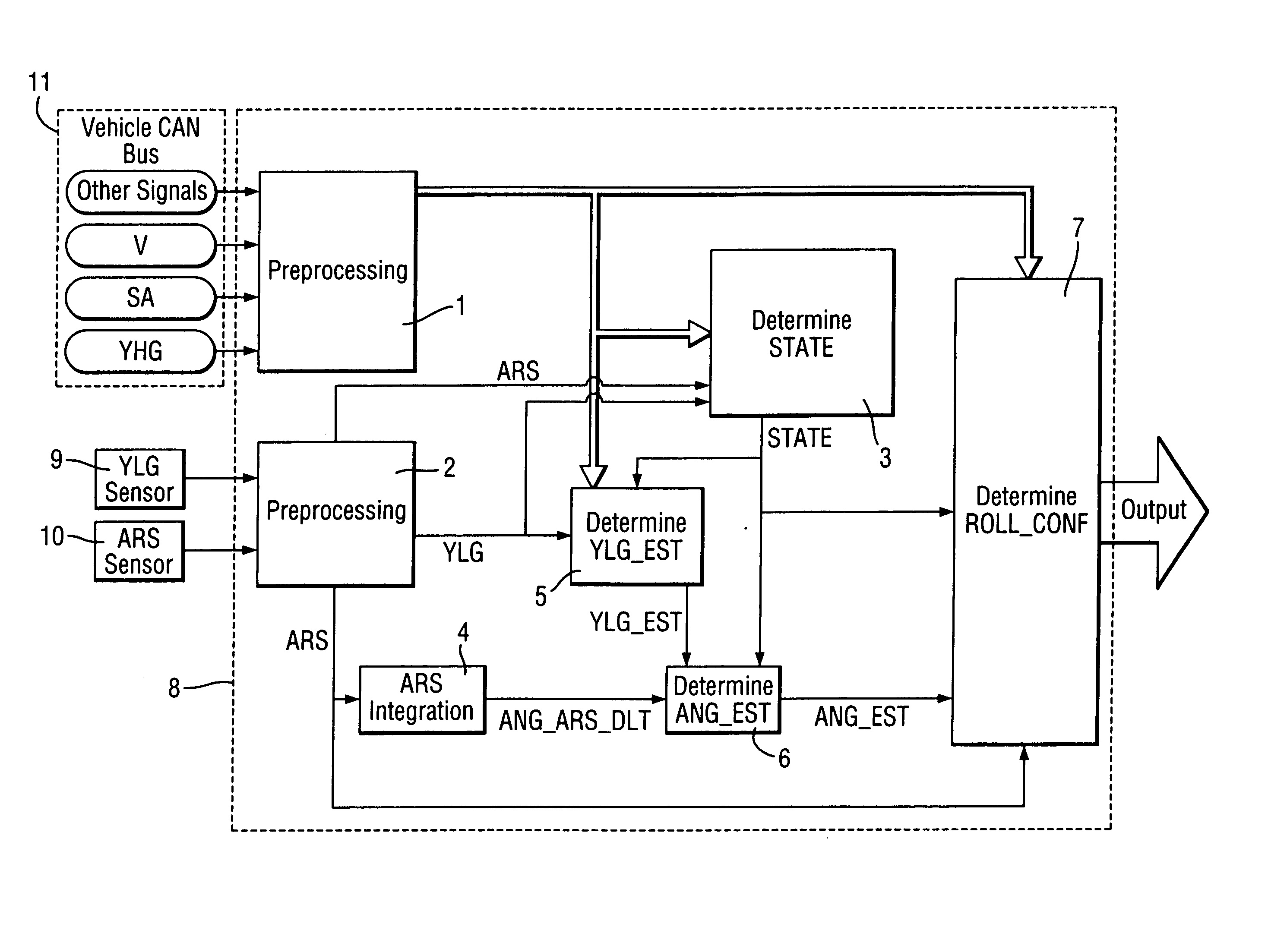
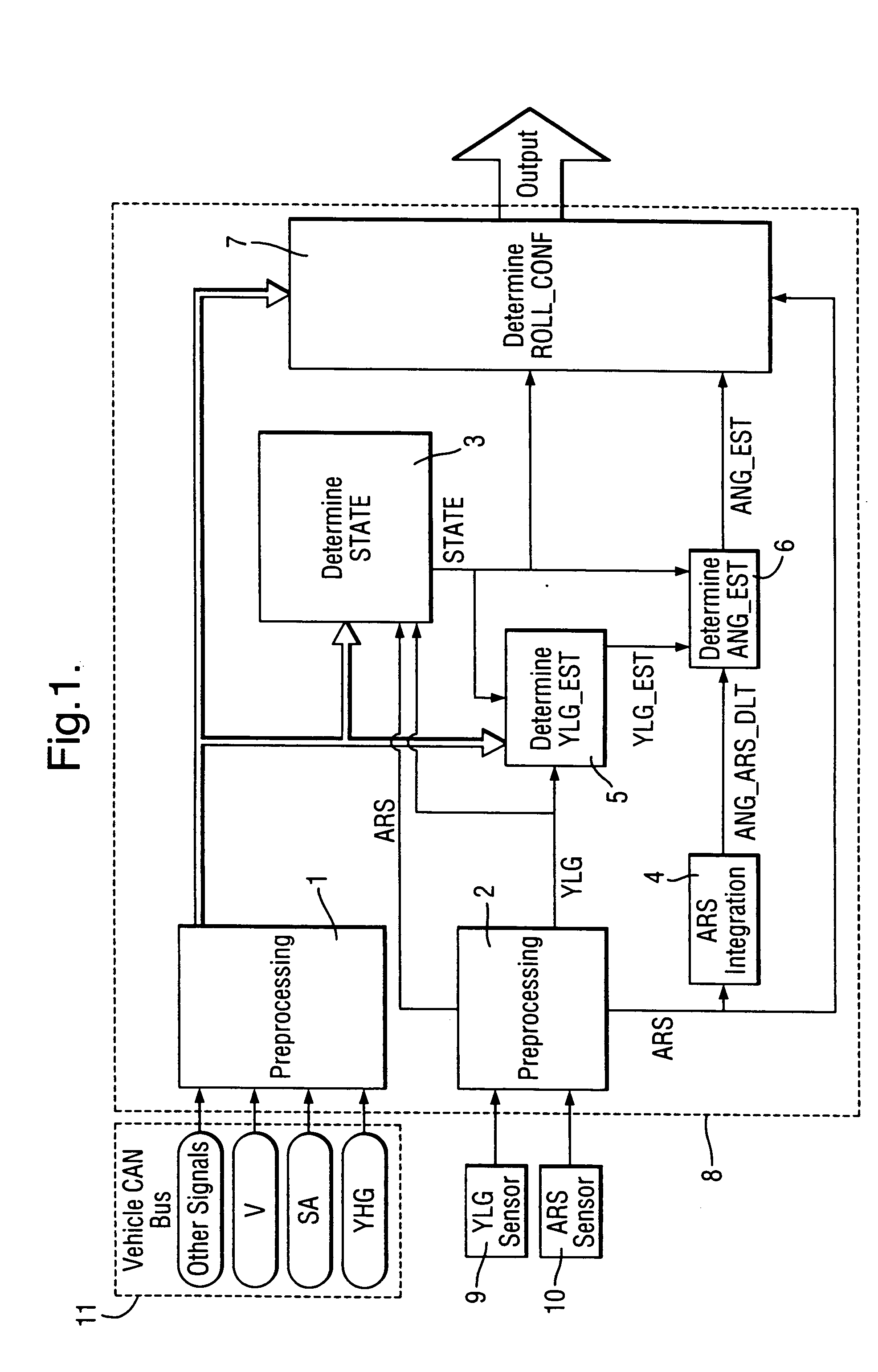
[0028] An exemplary microcontroller 8 implementation of the present invention is shown in FIG. 1, where all the essential features of the invention are implemented as a modular system comprising seven electronic circuits or processing blocks 1 to 7, cross linked with each other as described below. It is to be understood, however that other, in particular software implementations of the invention are possible as well.

[0029] The microcontroller 8 comprising processing blocks 1 to 7 is connected to vehicle lateral acceleration (YLG) sensor 9 and vehicle roll rate (ARS) sensor 10. Furthermore, the microcontroller 8 receives the vehicle velocity (V), additional high-g lateral acceleration (YHG) and vehicle steering angle (SA) signals from the vehicle communication bus 11.

[0030] The preferable ranges and resolutions of the ARS and YLG sensors are presented in the Table 1 below.

TABLE 1SensorSensorRangeResolutionARS−200 . . . 200 deg / s0.5 deg / sYLG−2 . . . 2 g0.01 g

[0031] Blocks 1 and 2 ...


PUM


Abstract

The present invention relates to a method and system for detecting a vehicle rollover or dangerous situations that may precede a rollover of a vehicle. The method comprises the steps of (a) measuring the set of input signals including at least vehicle velocity, vehicle steering angle, vehicle lateral acceleration, and vehicle roll rate; (b) integrating the vehicle roll rate to obtain the vehicle roll angle increment; (c) determining the vehicle state on the basis of the input signals; (d) determining the vehicle estimated lateral acceleration, corresponding to the vehicle true roll angle, on the basis of at least the vehicle state, vehicle lateral acceleration and the centrifugal acceleration; (e) determining the vehicle estimated roll angle on the basis of at least the vehicle roll angle increment, the vehicle estimated lateral acceleration and the vehicle state; and (f) generating an output activation signal determining a possibility of rollover of the vehicle, as a function of at least: vehicle estimated roll angle and the vehicle roll rate.

Description

TECHNICAL FIELD [0001] The present invention relates to a method and system for detecting a vehicle rollover or dangerous situations that may precede a rollover of a vehicle. BACKGROUND OF THE INVENTION [0002] The purpose of the rollover detection system is activation of protection devices such as seat belts pretensioners, pop-up rollover bars or air bags, especially air bags protecting occupants during rollover accident. [0003] There are number of ways for detecting rollover events. The most of the current systems use angular rate sensor (ARS) for calculating vehicle angle with respect to the horizontal plane. In such solutions, the algorithm numerically integrates the time dependent roll rate signal and provides the roll rate based angle as an output. As the ARS sensor signal always contains some errors (e.g. sensor drift, noise, etc.), these errors are accumulated during the integration process. As a result, the long term integration of ARS signal, without additional corrective m...

Claims


Application Information

Patent Timeline
Patent Type & Authority Applications(United States)
IPC IPC(8): B60G17/005
CPCB60R21/0132B60R2021/01313B60R2021/01327B60R21/0133
Inventor GEBOREK, MARIUSZSYGNAROWICZ, DANIEL
Owner APTIV TECH LTD
Why Eureka
Try Eureka