Microcomputer and trace control method capable of tracing desired task

a microcomputer and task technology, applied in the field of microcomputers and trace control methods, can solve the problems of requiring an extra space for storing excess trace data, significant drop in debug efficiency, and affecting so as to avoid memory space shortage and improve the efficiency of user debug operation.

Inactive Publication Date: 2006-04-06
FUJITSU LTD
View PDF6 Cites 23 Cited by
  • Summary
  • Abstract
  • Description
  • Claims
  • Application Information

AI Technical Summary

Benefits of technology

[0026] According to at least one embodiment of the invention, during the development of a system using a microcomputer, the debugger specifies information about a task to be traced at the time of debugging, thereby making it possible to collect only the trace information about a desired task. Thi

Problems solved by technology

This results in a significant drop in debug efficiency.
Accordingly, the trace data of the task of interest for debugging ends up being buried in the trace data of the other tasks, resulting in a significant drop in debug efficiency.
Further, this ends up requiring an extra space for storing excess trace data.
In the microcomputers, the essential circuit portion for providing the function of the microcomputer such as a CPU and cache memories occupies a large circuit area, so that a trace memory for use in storing trace data cannot be provided with large capacity.
Accordingly, an attempt to store all the trace data in the trace memory provided inside the chip results in the memory space being insufficient for the purpose of analyzing the operation of a routine to be debugged.
In the system in which the trace data is consecutively output to the ICE provided outside the chip, it becomes increasingly difficult

Method used


Image

  • Microcomputer and trace control method capable of tracing desired task
  • Microcomputer and trace control method capable of tracing desired task
  • Microcomputer and trace control method capable of tracing desired task

Examples


Embodiment Construction

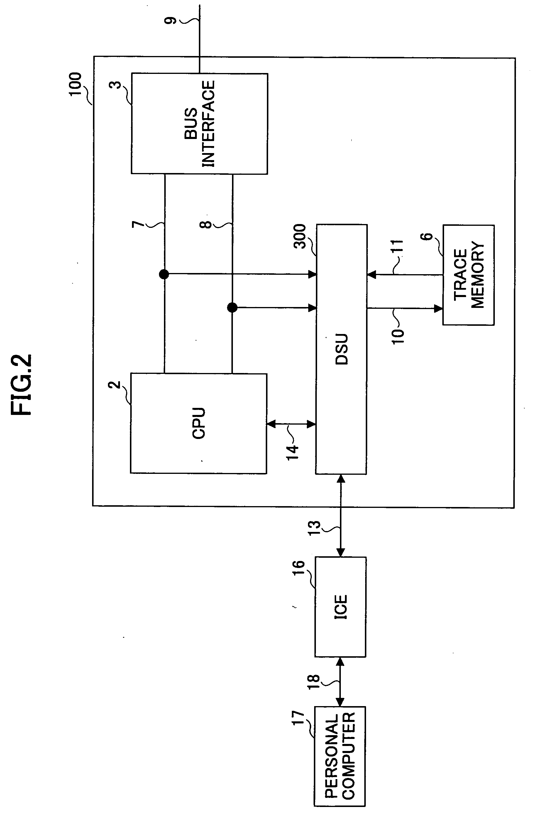
[0038]FIG. 2 is a block diagram showing an example of the configuration of a debugging system according to the present invention. In FIG. 2, the same elements as those of FIG. 1 are referred to by the same numerals.

[0039] The debugging system of FIG. 2 includes a microcomputer 100 serving as an evaluation-purpose chip of the present invention, the ICE 16 for debugging the evaluation-purpose chip, and the personal computer 17 which controls the ICE 16 based on debugger software. The general-purpose communication cable 18 such as a USB couples between the personal computer 17 and the ICE 16. The tool bus 13, which is an interface for emulation, couples between the ICE 16 and the microcomputer 100.

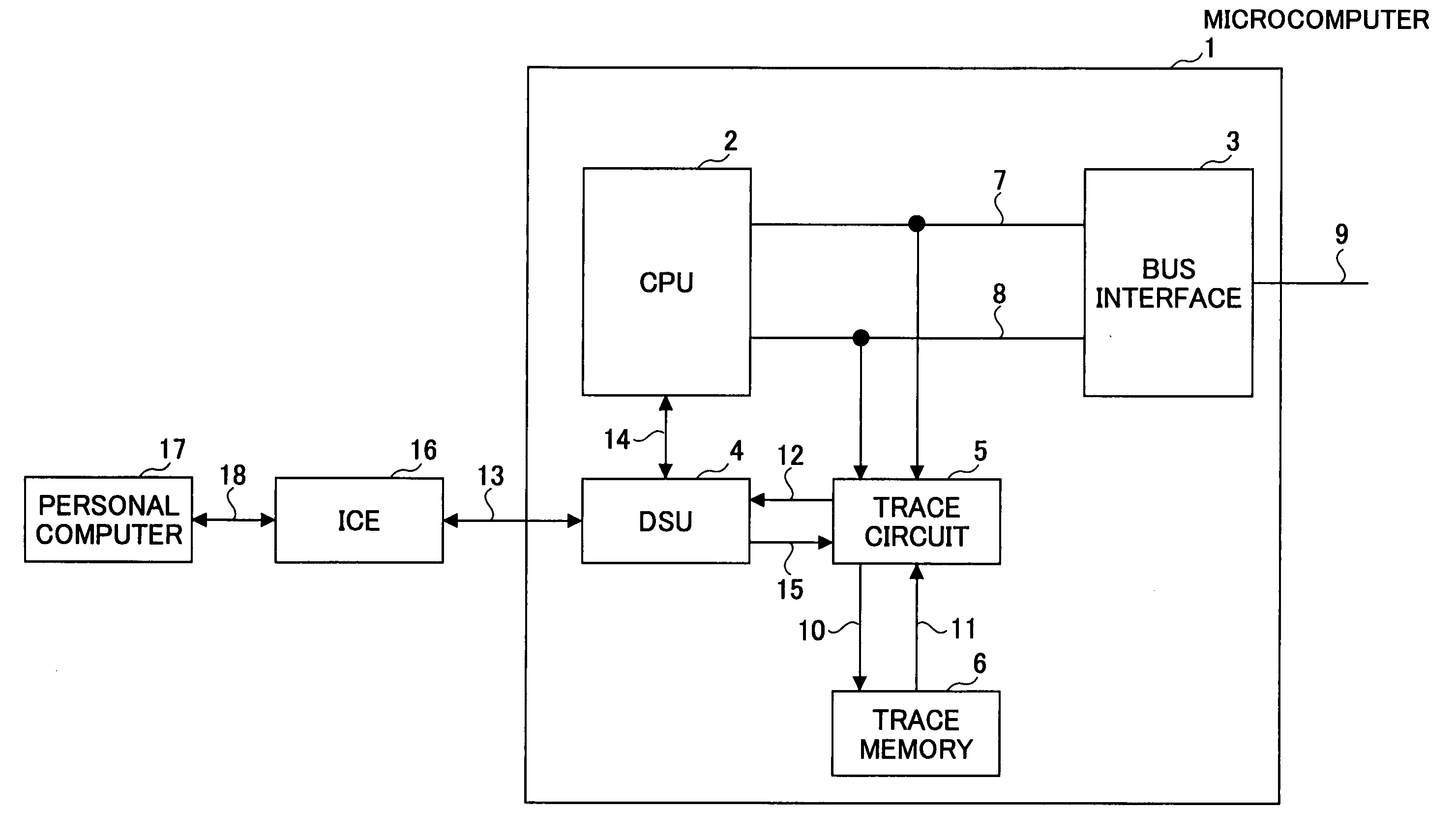
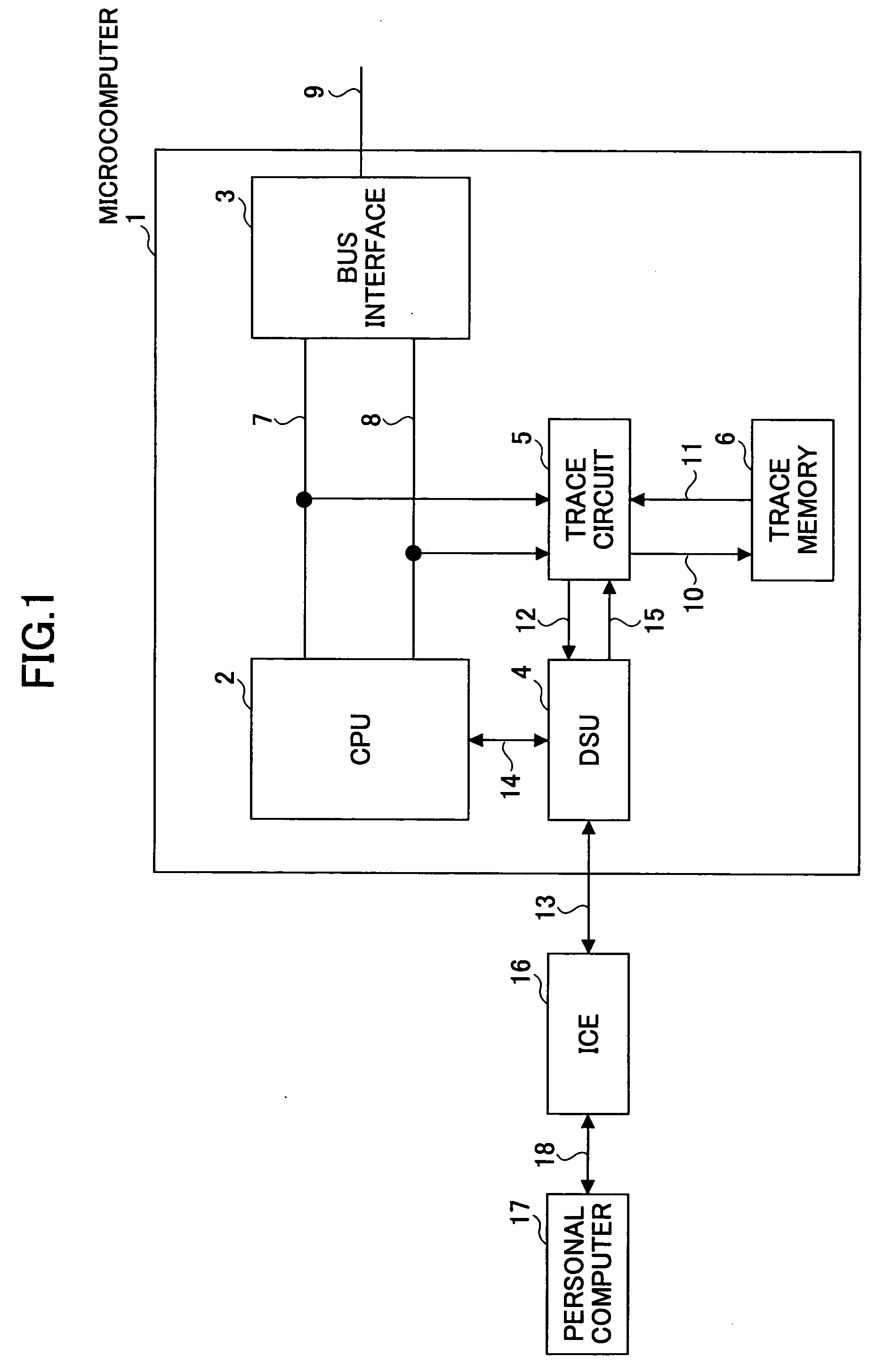
[0040] The microcomputer 100 includes the CPU 2, the bus interface 3, a debug support unit (hereinafter referred to as a DSU) 300 coupled to the ICE 16 through the tool bus 13, the trace memory 6, the command bus 7, and the data bus 8. The bus interface 3 is an interface for unifying the co...


PUM


Abstract

A microcomputer includes a bus, a CPU coupled to the bus, a trace data generating circuit coupled to the bus to output trace data of a process executed by the CPU at an output node, a memory coupled to the output node of the trace data generating circuit to store the trace data, a first register coupled to the bus to store a task number indicative of a task being executed by the CPU, and a control unit coupled to the first register to control on/off of outputting of the trace data from the trace data generating circuit in response to the task number.

Description

CROSS-REFERENCE TO RELATED APPLICATIONS [0001] The present application is based upon and claims the benefit of priority from the prior Japanese Patent Application No. 2004-273941 filed on Sep. 21, 2004, with the Japanese Patent Office, the entire contents of which are incorporated herein by reference. BACKGROUND OF THE INVENTION [0002] 1. Field of the Invention [0003] The present invention generally relates to microcomputers and trace control methods, and particularly relates to a microcomputer and trace control method that are capable of controlling the on / off state of trace operations. [0004] 2. Description of the Related Art [0005] When a system using a microcomputer is to be developed, an evaluation-purpose chip (evaluation chip) is produced. Unlike microcomputer chips for mass production, the evaluation-purpose chip is equipped with the interface and RAM for use in emulation. Debugging is then performed with respect to the evaluation-purpose chip, which operates in the same man...

Claims


Application Information

Patent Timeline
IPC IPC(8): G06F11/00
CPCG06F11/364
Inventor TAGAWA, KOUTAROU
Owner FUJITSU LTD
Why Eureka
Try Eureka