
Temperature measuring device using a matrix switch, a semiconductor package and a cooling system

a temperature measurement and matrix switch technology, applied in semiconductor/solid-state device details, ventilation systems, domestic cooling apparatus, etc., can solve the problems of high power consumption of high-performance semiconductor packages, damage to semiconductor packages, heat sinks or fans used, etc., to achieve effective measurement of temperatures

Inactive Publication Date: 2006-04-13
SAMSUNG ELECTRONICS CO LTD
View PDF5 Cites 24 Cited by
  • Summary
  • Abstract
  • Description
  • Claims
  • Application Information

AI Technical Summary

Benefits of technology

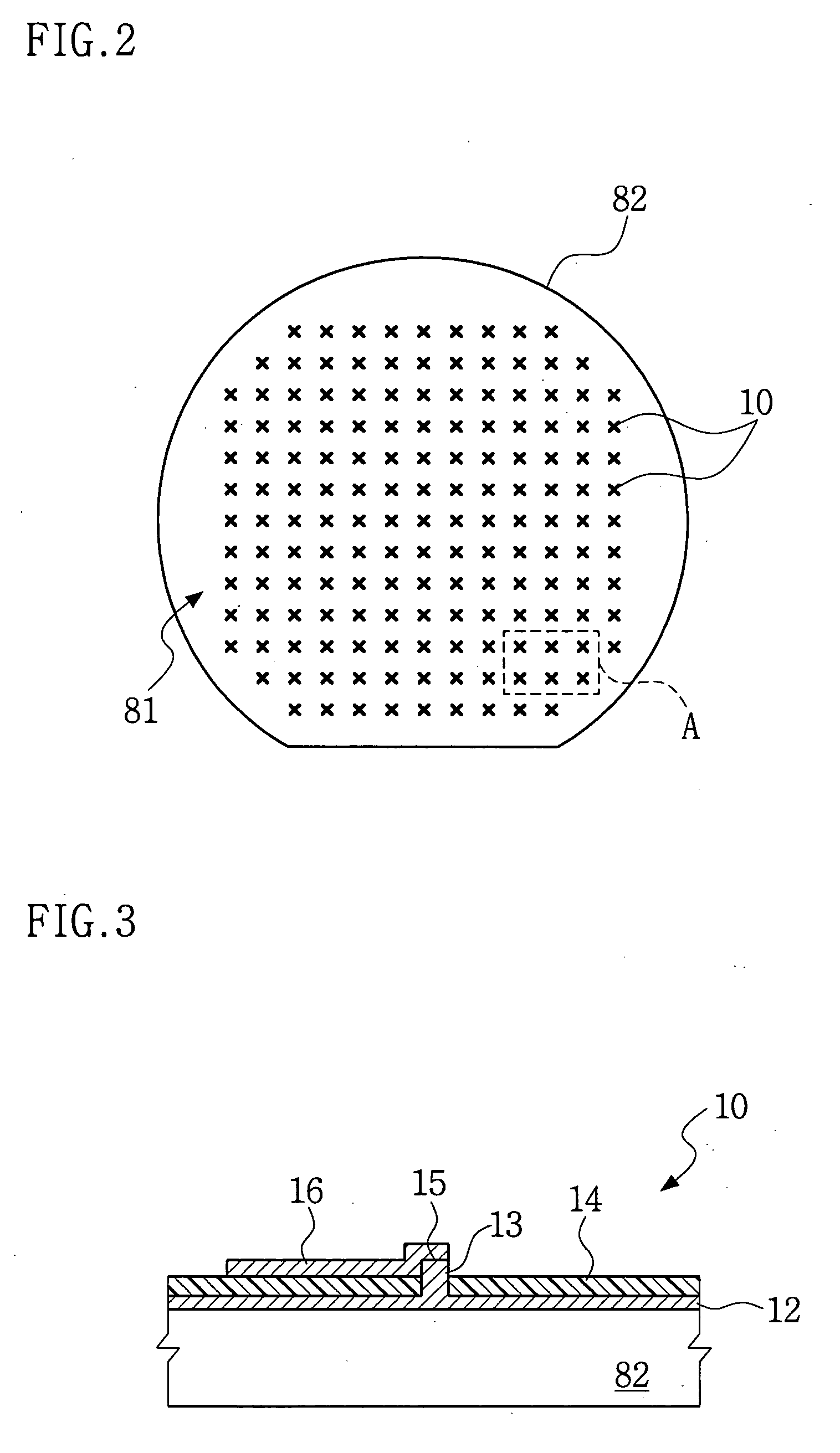
[0019] Another exemplary embodiment of the present invention is directed to effectively measuring temperatures without forming complicated wiring on the surface of a semiconductor or other device.

Problems solved by technology

High performance semiconductor packages operate with high power consumption.
This increased operating power generates heat, which, if not properly dissipated, may result in damage to the semiconductor packages.
The heat sink or fan used may be insufficient for effectively preventing the hot spot.
This method may not estimate the temperature of a wafer during a desired process, but only the maximum temperature after the process.
However, the device of this Japanese prior art may have a many contacts electrically connected to each other.
Thus it is difficult to precisely measure the temperature at a specific contact due to adjacent contacts.
For example, as the number of the temperature sensors increases, the hard wire connections become more complicated, and the hard wires are more apt to breakage.
In practice, it is not practical to form hard wires over the entire surface of a wafer.
Thus, it is difficult to precisely measure the temperature of the entire surface of the wafer or a semiconductor chip.
The apparatus of the Korean prior art may have a wiring portion which may be complicated and occupy a larger area than the contact portion.
Consequently, the contact portion may be limited to certain positions and areas.
Thus it is difficult to measure the temperature of the entire surface of the wafer and a semiconductor chip.

Method used


Image

  • Temperature measuring device using a matrix switch, a semiconductor package and a cooling system
  • Temperature measuring device using a matrix switch, a semiconductor package and a cooling system
  • Temperature measuring device using a matrix switch, a semiconductor package and a cooling system

Examples


Embodiment Construction

[0034] Exemplary, non-limiting embodiments of the present invention will now be described more fully hereinafter with reference to the accompanying drawings. This invention may, however, be embodied in many different forms and should not be construed as limited to the exemplary embodiments set forth herein. Rather, the disclosed embodiments are provided so that this disclosure will be thorough and complete, and will fully convey the scope of the invention to those skilled in the art. The principles and feature of this invention may be employed in varied and numerous embodiments without departing from the scope of the invention.

[0035] It should be noted that these figures are intended to illustrate the general characteristics of methods and devices of exemplary embodiments of this invention, for the purpose of the description of such exemplary embodiments herein. These drawings are not, however, to scale and may not precisely reflect the characteristics of any given embodiment, and ...


PUM


Abstract

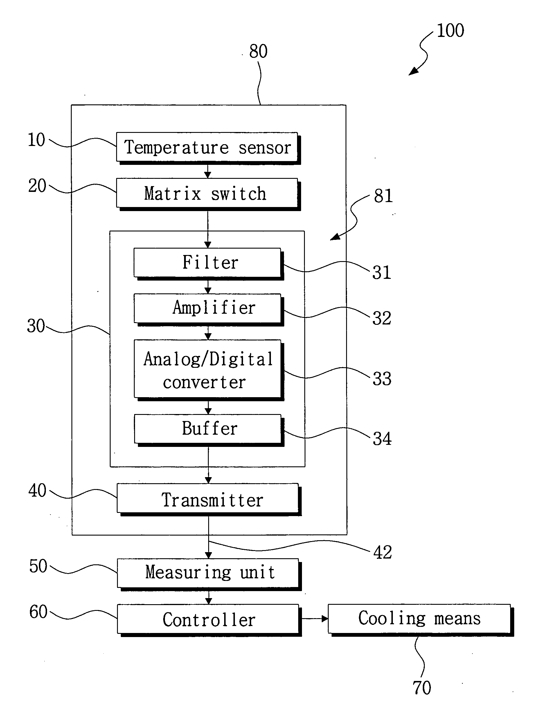
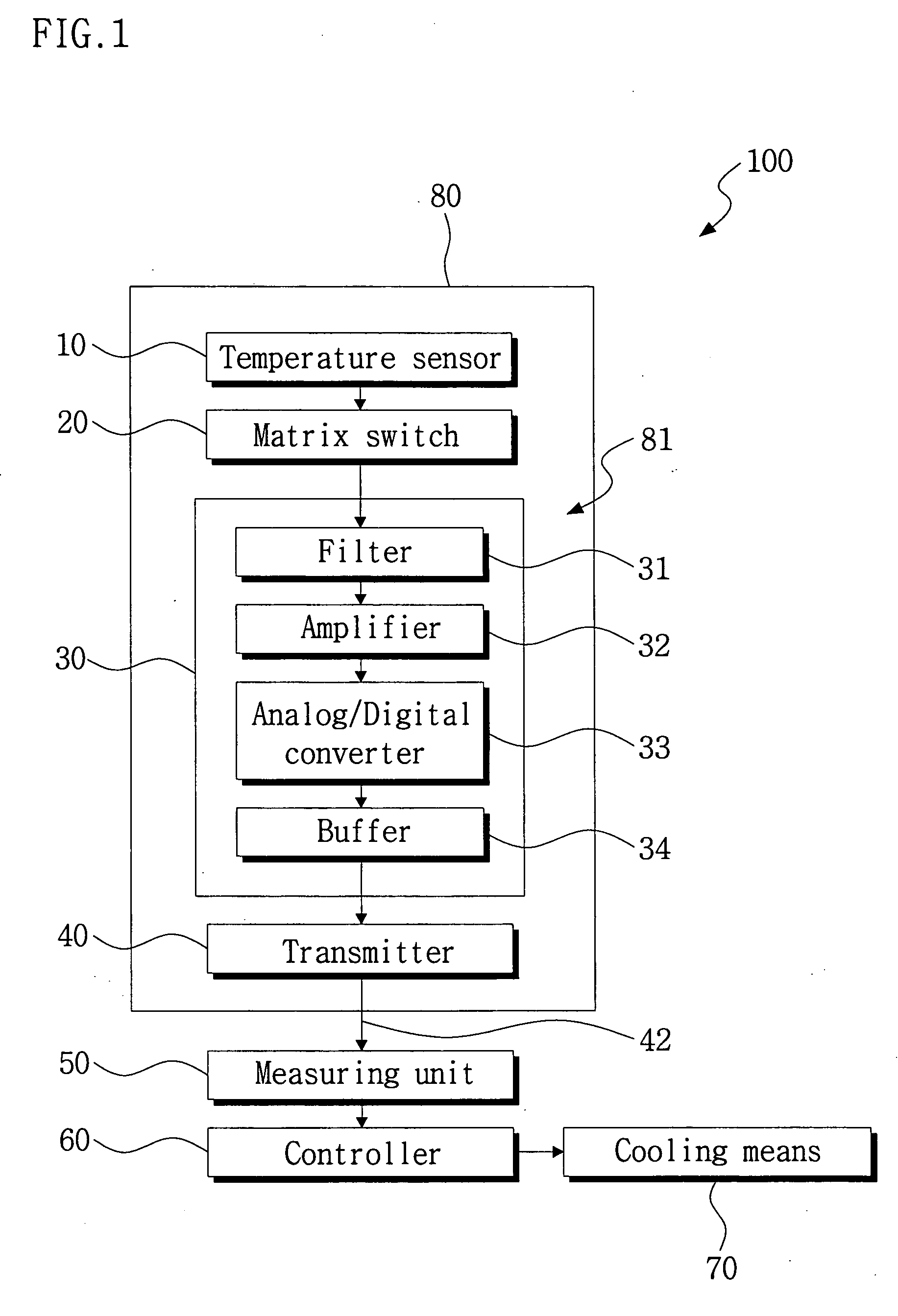
An embodiment relates to a temperature measuring device using a matrix switch, and a semiconductor package. In another embodiment a cooling system may be included. A plurality of temperature sensors may be arranged on a surface of a semiconductor device. The matrix switch may select the temperature sensors by an address method to form a circuit that includes the selected temperature sensor. A measuring unit may receive an output signal of the selected temperature sensor to calculate the temperature at the selected temperature sensor.

Description

CROSS REFERENCE TO RELATED APPLICATIONS [0001] This U.S. non-provisional application claims benefit of priority under 35 U.S.C. §119 of Korean Patent Application No. 2004-81309, filed on Oct. 12, 2004, the entire contents of which are incorporated herein by reference. BACKGROUND OF THE INVENTION [0002] 1. Field of the Invention [0003] The present invention relates to a semiconductor device and, more particularly, to a temperature measuring device using a matrix switch, a semiconductor package and a cooling system. [0004] 2. Description of the Related Art [0005] High performance semiconductor packages operate with high power consumption. Newer, higher performing semiconductor packages use even more power. This increased operating power generates heat, which, if not properly dissipated, may result in damage to the semiconductor packages. [0006] To dissipate the heat which may occur during operation of a semiconductor chip, semiconductor devices such as microprocessors, memory devices,...

Claims


Application Information

Patent Timeline
Patent Type & Authority Applications(United States)
IPC IPC(8): F25B21/02F25D23/12H01L35/28F24F7/00
CPCH01L22/34H01L23/34H01L2924/0002H01L2924/00H01L22/00
Inventor IM, YUN-HYEOKKANG, SUK-CHAELEE, HEE-SEOK
Owner SAMSUNG ELECTRONICS CO LTD
Learn More