Method for operating an internal combustion engine
What is AI technical title?
AI technical title is built by Patsnap AI team. It summarizes the technical point description of the patent document.
a technology of internal combustion engine and combustion chamber, which is applied in the direction of machines/engines, electric control, fuel injection pumps, etc., can solve the problems of reducing the maximum temperature, increasing the particle emission, and reducing efficiency
Inactive Publication Date: 2008-08-26
AVL LIST GMBH
View PDF22 Cites 17 Cited by
Summary
Abstract
Description
Claims
Application Information
AI Technical Summary
This helps you quickly interpret patents by identifying the three key elements:
Problems solved by technology
Method used
Benefits of technology
Benefits of technology
The patent text describes a method for operating an internal combustion engine to reduce emissions of particulate matter and nitrogen oxides. The method involves controlling the phase of combustion, or ignition, by advancing the start of injection and controlling the amount of fuel injected. The method also involves regulating the air-fuel mixture and the amount of exhaust gas recirculation to optimize combustion. The text describes various methods for controlling these factors, such as the Homogeneous Charge Compression Ignition (HCCI) method and the Piston Recess with Constriction (PR) method. The technical effects of these methods include improved fuel conditioning, reduced combustion noise, improved engine efficiency, and reduced emissions of particulate matter and nitrogen oxides.
Problems solved by technology
Since the homogenization of fuel and air is time-dependent, this method is limited as regards engine speed and load, and particle emission will increase if homogenization is insufficient.
It is disadvantageous that especially in the medium load region a low air ratio combines with low combustion temperature and thus efficiency is lost.
The back-shifting of the combustion process causes a reduction of maximum temperature, but at the same time leads to an increase of mean temperature at a certain late crank angle, which results in an increased burning of particulates.
In internal combustion engines operated according to the HCLI or the HPLI-method such piston types with a deep and constricted piston recess have not been used up to now, since it was assumed that start-up behaviour and thermodynamic efficiency would strongly deteriorate due to the deep piston recess and the strong squish flow.
Method used
Image
Click on the blue label to locate the original text in one second.
Reading with bidirectional positioning of images and text.
Examples
Embodiment Construction
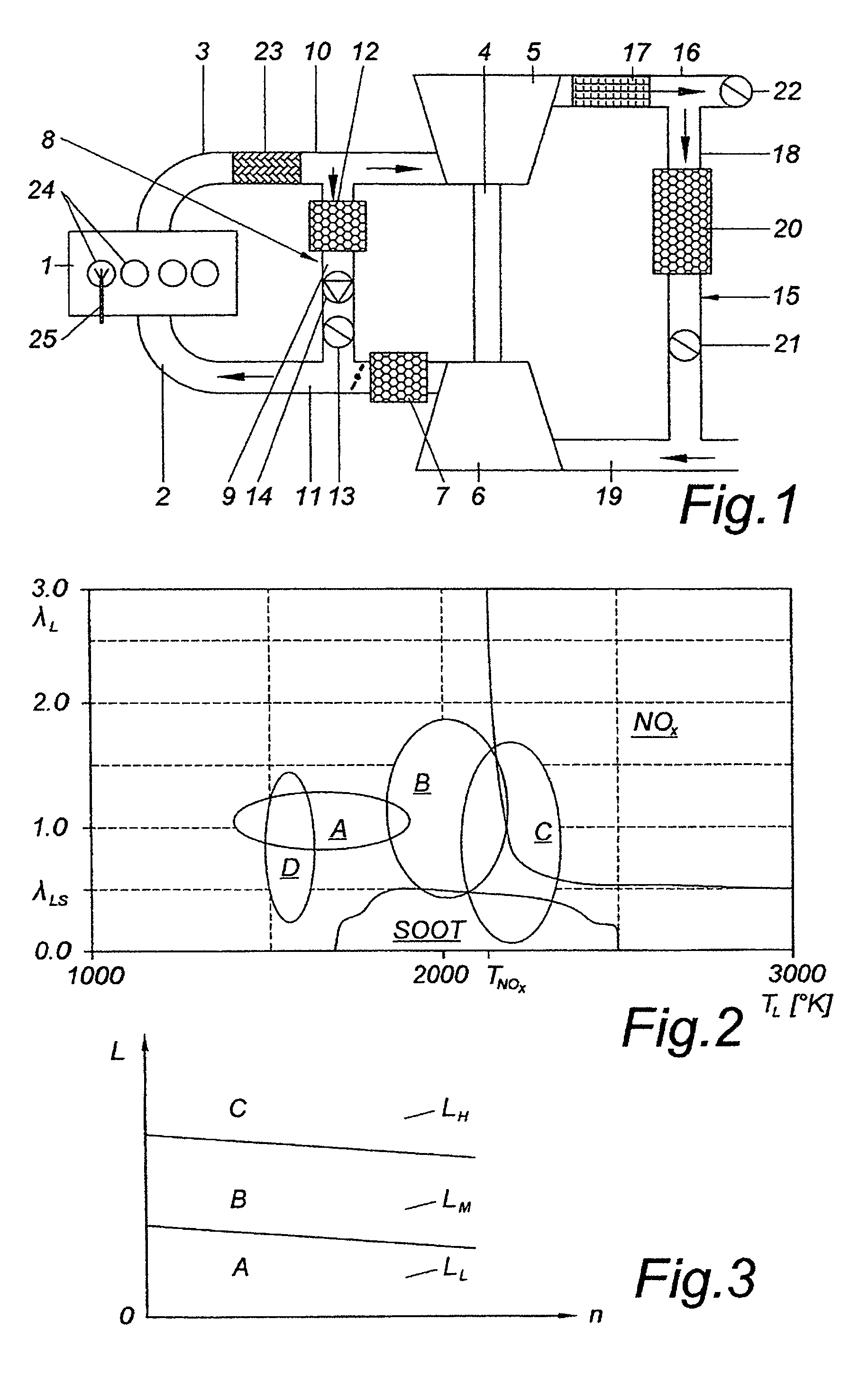
[0071]FIG. 1 shows an internal combustion engine 1 with an intake manifold 2 and an exhaust manifold 3. The internal combustion engine 1 is charged by an exhaust gasturbocharger 4 comprising an exhaust-gas-driven turbine 5 and a compressor 6 driven by the turbine 5. On the intake side an intercooler 7 is placed following the compressor 6 in flow-direction.
[0072]Furthermore a high-pressure exhaust gas recirculation system 8 with a first exhaust gas recirculation line 9 is provided between the exhaust gas line 10 and the intake line 11. The exhaust gas recirculationsystem 8 comprises an exhaust gas recirculation cooler 12 and an exhaust gas recirculation valve 13. Depending on the pressure difference between the exhaust line 10 and the intake line 11 an exhaust gas pump 14 may be provided in the exhaust gas recirculation line 9 in order to control or increase the exhaust gas recirculation rate.
[0073]In addition to this high-pressure exhaust gas recirculation system 8 a low-pressure ...
PUM
Abstract
The invention relates to a direct-injection internal combustion engine that is operated in a first operating range associated with the low part load, with largely homogeneous combustion of the mixture and subsequent injection. Said internal combustion engine is operated in a second operating range associated with the middle part load, with low-temperature combustion of the mixture. In this way, minimum nitrogenoxide and soot emissions and a high degree of efficiency can be achieved both in the lower part load region and up to the full load region.
Description
BACKGROUND OF THE INVENTION[0001]1. Field of the Invention[0002]The invention relates to a method for operating an internal combustion engine, in particular a diesel engine, and to an internal combustion engine suitable for implementing the method.[0003]2. The Prior Art[0004]The most important variables governing the combustion process in a combustion engine with internal combustion are the phase of the course of combustion, or rather the beginning of combustion, the maximum rate of increase of cylinder pressure, and the peak cylinder pressure.[0005]In an internal combustion engine in which combustion occurs essentially by self-ignition of a directly injected volume of fuel, the governing variables are largely determined by injection timing, charge composition, and ignition lag. These parameters in turn depend on a multitude of variables, such as engine speed, amount of fuel, intake temperature, charge pressure, effective compression ratio, amount of inert gas in the cylinder charge...
Claims
Application Information
Patent Timeline
Application Date:The date an application was filed.
Publication Date:The date a patent or application was officially published.
First Publication Date:The earliest publication date of a patent with the same application number.
Issue Date:Publication date of the patent grant document.
PCT Entry Date:The Entry date of PCT National Phase.
Estimated Expiry Date:The statutory expiry date of a patent right according to the Patent Law, and it is the longest term of protection that the patent right can achieve without the termination of the patent right due to other reasons(Term extension factor has been taken into account ).
Invalid Date:Actual expiry date is based on effective date or publication date of legal transaction data of invalid patent.

